Create Panorama
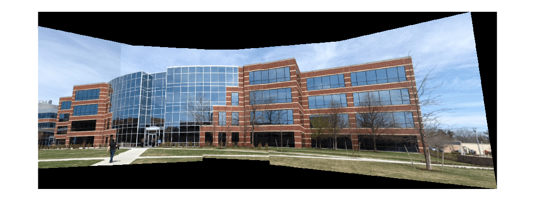
This example shows how to automatically stitch multiple images into panorama. The procedure for image stitching is an extension of feature based image registration. Instead of registering a single pair of images, multiple image pairs are successively registered relative to each other to form a panorama.
Load Images
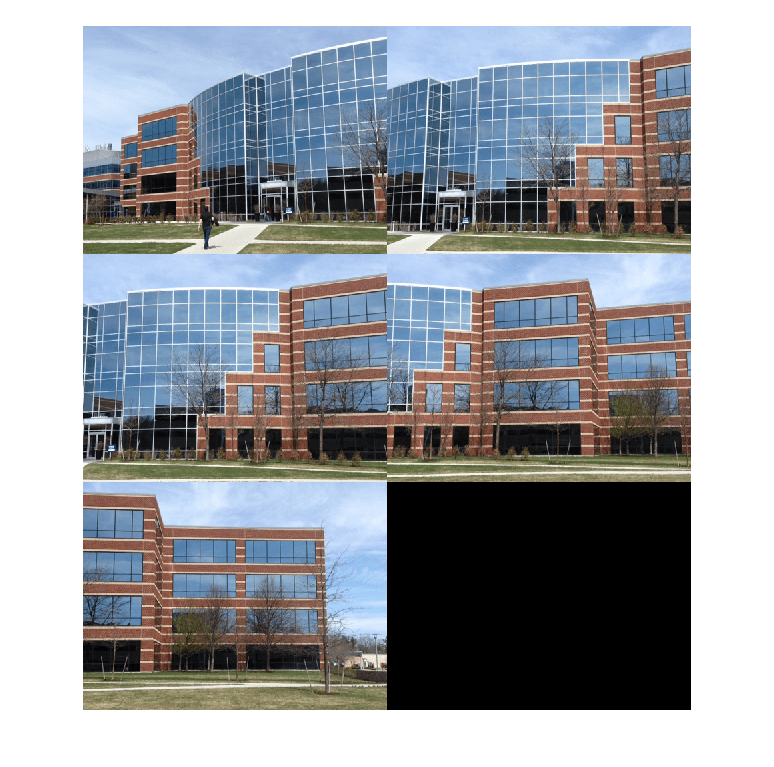
The image set used in this example contains pictures of a building. These were taken with an uncalibrated smart phone camera by sweeping the camera from left to right along the horizon, capturing all parts of the building. The images are relatively unaffected by any lens distortion so camera calibration was not required. However, if lens distortion is present, the camera should be calibrated and the images undistorted prior to creating the panorama. Use the Camera Calibrator app to calibrate a camera if needed.
Load and display images.
buildingDir = fullfile(toolboxdir("vision"),"visiondata","building");
buildingScene = imageDatastore(buildingDir);

montage(buildingScene.Files)

Register Image Pairs
To create the panorama, start by registering successive image pairs using the following procedure:
Detect and match features between and .
Estimate the geometric transformation, , that maps to .
Compute the transformation that maps into the panorama image as .
Read the first image from the image set.
I = readimage(buildingScene,1);
Initialize features for the first image.
grayImage = im2gray(I);
points = detectSURFFeatures(grayImage);
[features,points] = extractFeatures(grayImage,points);
Initialize all the transformations to the identity matrix. Note that the projective transformation is used because the building images are fairly close to the camera. For scenes captured from a further distance, consider using affine transformations.
numImages = numel(buildingScene.Files);
tforms(numImages) = projtform2d;
Initialize variable to hold image sizes.
imageSize = zeros(numImages,2);
Iterate over remaining image pairs. For each image, store the points and features from the previous image. Read then convert it to grayscale and save the image size. Detect and extract SURF features from the image and find correspondences between it and the previous image. Then, estimate the transformation between the two correspondences.
for n = 2:numImages
    pointsPrevious = points;
    featuresPrevious = features;

    I = readimage(buildingScene, n);
    grayImage = im2gray(I);
    imageSize(n,:) = size(grayImage);

    points = detectSURFFeatures(grayImage);
    [features,points] = extractFeatures(grayImage,points);

    indexPairs = matchFeatures(features,featuresPrevious,Unique=true);
    matchedPoints = points(indexPairs(:,1), :);
    matchedPointsPrev = pointsPrevious(indexPairs(:,2), :);

    tforms(n) = estgeotform2d(matchedPoints, matchedPointsPrev,...
        "projective",Confidence=99.9,MaxNumTrials=2000);

    tforms(n).A = tforms(n-1).A * tforms(n).A;
end
At this stage, all transformations in tforms are relative to the first image, a method that simplified the coding of the image registration procedure by enabling sequential processing of the images. However, starting the panorama with the first image often leads to a less aesthetically pleasing result, as it tends to distort most of the images comprising the panorama. A more visually appealing panorama can be achieved by adjusting the transformations so that the center of the scene undergoes the least distortion. This improvement involves inverting the transformation for the center image and applying this inverted transformation to all other images. Start by using the projtform2d outputLimits method to find the output limits for each transformation. The output limits are then used to automatically find the image that is roughly in the center of the scene.
Compute the output limits for each transformation.
for idx = 1:numel(tforms)
    [xlim(idx,:),ylim(idx,:)] = outputLimits(tforms(idx),[1 imageSize(idx,2)],[1 imageSize(idx,1)]);
end
Next, compute the average X limits for each transformation and find the image that is in the center. Only the X limits are used here because the scene is known to be horizontal. If another set of images are used, both the X and Y limits may need to be used to find the center image.
avgXLim = mean(xlim, 2);
[~,idx] = sort(avgXLim);
centerIdx = floor((numel(tforms)+1)/2);
centerImageIdx = idx(centerIdx);
Finally, apply the center image's inverse transformation to all the others.
Tinv = invert(tforms(centerImageIdx));
for idx = 1:numel(tforms)
    tforms(idx).A = Tinv.A * tforms(idx).A;
end
Initialize the Panorama
Create an initial, empty, panorama into which all the images are mapped. Use the outputLimits method to compute the minimum and maximum output limits over all transformations. These values are used to automatically compute the size of the panorama.
for idx = 1:numel(tforms)
    [xlim(idx,:),ylim(idx,:)] = outputLimits(tforms(idx),[1 imageSize(idx,2)],[1 imageSize(idx,1)]);
end
maxImageSize = max(imageSize);
Find the minimum and maximum output limits.
xMin = min([1; xlim(:)]);
xMax = max([maxImageSize(2); xlim(:)]);

yMin = min([1; ylim(:)]);
yMax = max([maxImageSize(1); ylim(:)]);
Compute the width and height of the panorama.
width  = round(xMax - xMin);
height = round(yMax - yMin);
Initialize the panorama with a blank canvas by setting up an array of zeros with dimensions [height width 3], matching the type and characteristics of the image, I.
panorama = zeros([height width 3],"like",I);Create the Panorama
Use imwarp to map images into the panorama and use imblend to overlay the images together.
Create a 2-D spatial reference object to define the size of the panorama.
xLimits = [xMin xMax];
yLimits = [yMin yMax];
panoramaView = imref2d([height width],xLimits,yLimits);
Create the panorama by warping each image to transform it into the panorama. Then generate a binary mask and overlay the warped image onto the panorama.
for idx = 1:numImages
    I = readimage(buildingScene,idx);
    warpedImage = imwarp(I,tforms(idx),OutputView=panoramaView);
    mask = imwarp(true(size(I,1),size(I,2)),tforms(idx),OutputView=panoramaView);
    panorama = imblend(warpedImage,panorama,mask,foregroundopacity=1);
end

imshow(panorama)

References
[1] Matthew Brown and David G. Lowe. 2007. Automatic Panoramic Image Stitching using Invariant Features. Int. J. Comput. Vision 74, 1 (August 2007), 59-73.