Fast Wavelet Transform (FWT) Algorithm
In 1988, Mallat produced a fast wavelet decomposition and reconstruction algorithm [1]. The Mallat algorithm for discrete wavelet transform (DWT) is, in fact, a classical scheme in the signal processing community, known as a two-channel subband coder using conjugate quadrature filters or quadrature mirror filters (QMFs).
The decomposition algorithm starts with signal s, next calculates the coordinates of A1 and D1, and then those of A2 and D2, and so on.
The reconstruction algorithm called the inverse discrete wavelet transform (IDWT) starts from the coordinates of AJ and DJ, next calculates the coordinates of AJ–1, and then using the coordinates of AJ–1 and DJ–1 calculates those of AJ–2, and so on.
This section addresses the following topics:
Filters Used to Calculate the DWT and IDWT
For an orthogonal wavelet, in the multiresolution framework, we start with the scaling function φ and the wavelet function ψ. One of the fundamental relations is the twin-scale relation (dilation equation or refinement equation):
All the filters used in DWT and IDWT are intimately related to the sequence
(wn)n∊Z
Clearly if φ is compactly supported, the sequence (wn) is finite and can be viewed as a filter. The filter W, which is called the scaling filter (nonnormalized), is
Finite Impulse Response (FIR)
Of length 2N
Of sum 1
Of norm
Of norm 1
A low-pass filter
For example, for the db3 scaling filter,
load db3
db3
    db3 =
    0.2352   0.5706   0.3252  -0.0955  -0.0604   0.0249

sum(db3)
    ans =
         1.0000

norm(db3)
    ans =
         0.7071
From filter W, we define four FIR filters, of length 2N and of norm 1, organized as follows.
Filters | Low-Pass | High-Pass |
|---|---|---|
Decomposition | Lo_D | Hi_D |
Reconstruction | Lo_R | Hi_R |
The four filters are computed using the following scheme.

where qmf is such that Hi_R and Lo_R are quadrature mirror filters (i.e., Hi_R(k)
= (–1) k Lo_R(2N +
1 – k)) for k = 1, 2,
..., 2N.
Note that wrev flips the filter coefficients.
So Hi_D and Lo_D are also quadrature mirror filters. The computation of these filters is performed
using orthfilt. Next, we illustrate these properties
with the db6 wavelet.
Load the Daubechies’ extremal phase scaling filter and plot the coefficients.
load db6;
subplot(421); stem(db6,'markerfacecolor',[0 0 1]);
title('Original scaling filter');
Use orthfilt to return the analysis
(decomposition) and synthesis (reconstruction) filters.
Obtain the discrete Fourier transforms (DFT) of the lowpass and highpass analysis filters. Plot the modulus of the DFT.
LoDFT = fft(Lo_D,64);
HiDFT = fft(Hi_D,64);
freq = -pi+(2*pi)/64:(2*pi)/64:pi;
subplot(427); plot(freq,fftshift(abs(LoDFT)));
set(gca,'xlim',[-pi,pi]); xlabel('Radians/sample');
title('DFT Modulus - Lowpass Filter')
subplot(428); plot(freq,fftshift(abs(HiDFT)));
set(gca,'xlim',[-pi,pi]); xlabel('Radians/sample');
title('Highpass Filter');

Algorithms
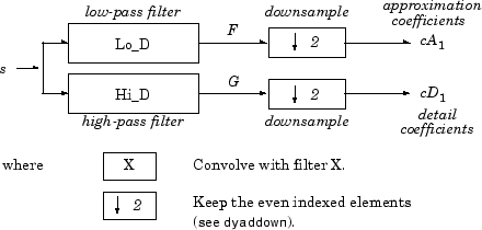
Given a signal s of length N, the DWT consists of log2N stages at most. Starting from s, the first step produces two sets of coefficients: approximation coefficients cA1, and detail coefficients cD1. These vectors are obtained by convolving s with the low-pass filter Lo_D for approximation, and with the high-pass filter Hi_D for detail, followed by dyadic decimation.
More precisely, the first step is

The length of each filter is equal to 2L. The result of convolving a length N signal with a length 2L filter is N+2L–1. Therefore, the signals F and G are of length N + 2L – 1. After downsampling by 2, the coefficient vectors cA1 and cD1 are of length
The next step splits the approximation coefficients cA1 in two parts using the same scheme, replacing s by cA1 and producing cA2 and cD2, and so on.

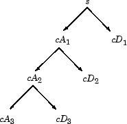
So the wavelet decomposition of the signal s analyzed at level j has the following structure: [cAj, cDj, ..., cD1].
This structure contains for J = 3 the terminal nodes of the following tree.

Conversely, starting from cAj and cDj, the IDWT reconstructs cAj–1, inverting the decomposition step by inserting zeros and convolving the results with the reconstruction filters.

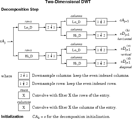
For images, a similar algorithm is possible for two-dimensional wavelets and scaling functions obtained from 1-D wavelets by tensorial product.
This kind of 2-D DWT leads to a decomposition of approximation coefficients at level j in four components: the approximation at level j + 1 and the details in three orientations (horizontal, vertical, and diagonal).
The following charts describe the basic decomposition and reconstruction steps for images.


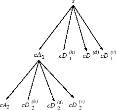
So, for J = 2, the 2-D wavelet tree has the following form.

Finally, let us mention that, for biorthogonal wavelets, the same algorithms hold but the decomposition filters on one hand and the reconstruction filters on the other hand are obtained from two distinct scaling functions associated with two multiresolution analyses in duality.
In this case, the filters for decomposition and reconstruction are, in general, of different odd lengths. This situation occurs, for example, for “splines” biorthogonal wavelets used in the toolbox. By zero-padding, the four filters can be extended in such a way that they will have the same even length.
Why Does Such an Algorithm Exist?
The previous paragraph describes algorithms designed for finite-length signals or images. To understand the rationale, we must consider infinite-length signals. The methods for the extension of a given finite-length signal are described in Border Effects.
Let us denote h = Lo_R and g = Hi_R and focus on the 1-D case.
We first justify how to go from level j to level j+1, for the approximation vector. This is the main step of the decomposition algorithm for the computation of the approximations. The details are calculated in the same way using the filter g instead of filter h.
Let (Ak(j))k∊Z be the coordinates of the vector Aj:
and Ak(j+1) the coordinates of the vector Aj+1:
Ak(j+1) is calculated using the formula
This formula resembles a convolution formula.
The computation is very simple.
Let us define
The sequence F(j+1) is the filtered output of the sequence A(j) by the filter .
We obtain
Ak(j+1) = F2k(j+1)
We have to take the even index values of F. This is downsampling.
The sequence A(j+1) is the downsampled version of the sequence F(j+1).
The initialization is carried out using Ak(0) = s(k), where s(k) is the signal value at time k.
There are several reasons for this surprising result, all of which are linked to the multiresolution situation and to a few of the properties of the functions φj,k and ψj,k.
Let us now describe some of them.
The family is formed of orthonormal functions. As a consequence for any j, the family is orthonormal.
The double indexed family
is orthonormal.
For any j, the are orthogonal to .
Between two successive scales, we have a fundamental relation, called the twin-scale relation.
Twin-Scale Relation for This relation introduces the algorithm's h filter . For more information, see Filters Used to Calculate the DWT and IDWT.
We check that:
The coordinate of φj+1,0 on φj,k is hk and does not depend on j.
The coordinate of φj+1,n on φj,k is equal to .
These relations supply the ingredients for the algorithm.
Up to now we used the filter h. The high-pass filter g is used in the twin scales relation linking the ψ and φ functions. Between two successive scales, we have the following twin-scale fundamental relation.
Twin-Scale Relation Between and
After the decomposition step, we justify now the reconstruction algorithm by building it. Let us simplify the notation. Starting from A1 and D1, let us study A0 = A1 + Dj1. The procedure is the same to calculate A = Aj+1 + Dj+1.
Let us define αn, δn, by
Let us assess the coordinates as
We will focus our study on the first sum the second sum is handled in a similar manner.
The calculations are easily organized if we note that (taking k = 0 in the previous formulas, makes things simpler)
If we transform the sequence into a new sequence defined by
..., α–1, 0, α0, 0, α1, 0, α2, 0, ... that is precisely
Then
and by extension
Since
the reconstruction steps are:
Replace the α and δ sequences by upsampled versions α˜ and inserting zeros.
Filter by h and g respectively.
Sum the obtained sequences.
1-D Wavelet Capabilities
Basic 1-D Objects
Objects | Description | |
|---|---|---|
Signal in original time | s Ak, 0 ≤ k ≤ j Dk, 1 ≤ k ≤ j | Original signal Approximation at level k Detail at level k |
Coefficients in scale-related time | cAk, 1 ≤ k ≤ j cDk, 1 ≤ k ≤ j [cAj, cDj, ..., cD1] | Approximation coefficients at level k Detail coefficients at level k Wavelet decomposition at level j, j ≥ 1 |
Analysis-Decomposition Capabilities
Purpose | Input | Output | File |
|---|---|---|---|
Single-level decomposition | s | cA1, cD1 | dwt |
Single-level decomposition | cAj | cAj+1, cDj+1 | dwt |
Decomposition | s | [cAj, cDj, ..., cD1] | wavedec |
Synthesis-Reconstruction Capabilities
Purpose | Input | Output | File |
|---|---|---|---|
Single-level reconstruction | cA1, cD1 | s or A0 | idwt |
Single-level reconstruction | cAj+1, cDj+1 | cAj | idwt |
Full reconstruction | [cAj, cDj, ..., cD1] | s or A0 | waverec |
Selective reconstruction | [cAj, cDj, ..., cD1] | Al, Dm | wrcoef |
Decomposition Structure Utilities
Purpose | Input | Output | File |
|---|---|---|---|
Extraction of detail coefficients | [cAj, cDj, ..., cD1] | cDk, 1 ≤ k ≤ j | detcoef |
Extraction of approximation coefficients | [cAj, cDj, ..., cD1] | cAk, 0≤ k ≤ j | appcoef |
Recomposition of the decomposition structure | [cAj, cDj, ..., cD1] | [cAk, cDk, ..., cD1] 1 ≤ k ≤ j | upwlev |
To illustrate command-line mode for 1-D capabilities, see 1-D Decimated Wavelet Analysis.
2-D Wavelet Capabilities
Basic 2-D Objects
Objects | Description | |
|---|---|---|
Image in original resolution | s | Original image |
A0 | Approximation at level 0 | |
Ak, 1 ≤ k ≤ j | Approximation at level k | |
Dk, 1 ≤ k ≤ j | Details at level k | |
Coefficients in scale-related resolution | cAk, 1 ≤ k ≤ j | Approximation coefficients at level k |
cDk, 1 ≤ k ≤ j | Detail coefficients at level k | |
[cAj, cDj, ..., cD1] | Wavelet decomposition at level j |
Dk stands for , the horizontal, vertical, and diagonal details at level k.
The same holds for cDk, which stands for .
The 2-D files are the same as those for the 1-D case, but with
a 2 appended on the end of the command.
For example, idwt becomes idwt2.
For more information, see 1-D Wavelet Capabilities.
To illustrate command-line mode for 2-D capabilities, see Wavelet Image Analysis and Compression..
References
[1] Mallat, S. G. “A Theory for Multiresolution Signal Decomposition: The Wavelet Representation,” IEEE Transactions on Pattern Analysis and Machine Intelligence. Vol. 11, Issue 7, July 1989, pp. 674–693.