DVB-S2 Symbol Demodulator
Demodulate complex constellation symbol to set of LLR values or data bits according to DVB-S2 standard
Since R2021b
Libraries:
Wireless HDL Toolbox /
Modulation
Description
The DVB-S2 Symbol Demodulator block demodulates complex data symbol to
log-likelihood ratio (LLR) values or data bits based on the modulation types supported by the
Digital Video Broadcast Satellite Second Generation (DVB-S2) standard [1]. The block accepts equalized
complex data symbols and a samplecontrol
bus or a valid
signal. It outputs demodulated LLR values or data bits and a samplecontrol
bus or a valid
signal based on the selected output type. The block provides
an option to select the output type as vector or scalar. The number of demodulated LLR values
or data bits for a given symbol depends on the modulation type, as this table shows.
Modulation Type | Number of LLR Values or Data Bits Per Symbol |
---|---|
π/2-BPSK | 1 |
QPSK | 2 |
8-PSK | 3 |
16-APSK | 4 |
32-APSK | 5 |
The block provides an architecture suitable for HDL code generation and hardware deployment. You can use this block in the development of a DVB-S2 receiver.
Examples
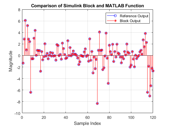
DVB-S2 Symbol Demodulation of Complex Data Symbols
Demodulate complex data symbols to LLRs or data bits.
Ports
Input
data — Data symbols
real-valued scalar | complex-valued scalar
Data symbols, specified as a real- or complex-valued scalar.
The software supports double
and
single
data types for simulation, but not for HDL code generation.
For HDL code generation, the input data type must be signed fixed
point
and the maximum input word length the block supports is 32
bits.
Data Types: single
| double
| int8
| int16
| int32
| signed fixed point
Complex Number Support: Yes
ctrl — Control signals accompanying sample stream
samplecontrol
bus
Control signals accompanying the sample stream, specified as a
samplecontrol
bus. The bus includes the start
,
end
, and valid
control signals, which indicate the
boundaries of the frame and the validity of the samples.
start
— Indicates the start of the input frameend
— Indicates the end of the input framevalid
— Indicates that the data on the input data port is valid
For more details, see Sample Control Bus.
Data Types: bus
valid — Indication of whether input data is valid
scalar
Control signal that indicates whether the input data is valid. When this value is
1
, the block accepts the values on the data
input port. When this value is 0
, the block ignores the values on
the data input port.
Dependencies
To enable this port, set the Output type parameter to
Scalar
.
Data Types: Boolean
modIdx — Modulation index
0
| 1
| 2
| 3
| 4
Modulation index, specified as 0
, 1
,
2
, 3
, or 4
. Each value
represents a specific modulation type, as the table shows.
Modulation Index | Modulation Type |
---|---|
0
| QPSK |
1 | 8-PSK |
2 | 16-APSK |
3 | 32-APSK |
4
| π/2-BPSK |
If you specify a value other than ones listed in this table, the block displays a
warning message and applies QPSK modulation. For HDL code generation, specify this
value in fixdt(0,3,0)
format.
Dependencies
To enable this port, set the Modulation source parameter to
Input port
.
Data Types: single
| double
| fixdt(0,3,0)
codeRateIdx — Code rate index
5
| 6
| 7
| 8
| 9
| 10
Code rate index, specified as 5
, 6
,
7
, 8
, 9
, or
10
. Each value represents a specific code rate, as this table
shows.
Code Rate Index | Code Rate |
---|---|
5
| 2/3 |
6 | 3/4 |
7 | 4/5 |
8 | 5/6 |
9
| 8/9 |
10 | 9/10 |
The code rates in this table apply to the modIdx input port
values 2
and 3
, which indicate 16-APSK and
32-APSK modulation, respectively. When you set the modIdx port
value to 0
, 1
, or 4
, the
block ignores the codeRateIdx input port values.
Specify this value in fixdt(0,4,0)
format.
Dependencies
To enable this port, set the Modulation source parameter to
Input port
.
Data Types: single
| double
| fixdt(0,4,0)
nVar — Noise variance
real-valued positive scalar
Noise variance, specified as a real-valued positive scalar.
This value must be of data type
fixdt(0,k,m)
, where
k is less than or equal to 16 and m is less
than or equal to k.
When the Output type parameter is set to
Scalar
, the block samples the nVar
port when the input valid is 1
.
When the Output type parameter is set to
Vector
, the block samples the nVar
port based on the samplecontrol
bus.
The software supports double
and
single
data types for simulation, but not for HDL code generation.
Dependencies
To enable this port, select the Enable noise variance input port parameter.
Data Types: single
| double
| uint8
| uint16
| unsigned fixed point
Output
data — Demodulated LLR values or data bits
scalar | eight-element real-valued column vector
Demodulated LLR values or data bits, returned as a scalar when the
Output type parameter is set to
Scalar
and as an eight-element real-valued column vector
when the Output type parameter is set to
Vector
.
When the Decision type parameter is set to
Approximate log-likelihood ratio
:For
double
andsingle
inputs, the output data type is the same as the input data type.For
fixed point
inputs, the block provides the output with an integer bit growth of 14 bits when you select the Enable noise variance input port parameter and with an integer bit growth of 3 bits when you clear the parameter.
When the Decision type parameter is set to
Hard
, the output data type isBoolean
for any supported input data type.
Data Types: single
| double
| int8
| int16
| int32
| Boolean
| fixed point
ctrl — Control signals accompanying sample stream
samplecontrol
bus
Control signals accompanying the sample stream, returned as a samplecontrol
bus. The bus includes the start
, end
, and
valid
control signals, which indicate the boundaries of the frame
and the validity of the samples.
start
— Indicates the start of the output frameend
— Indicates the end of the output framevalid
— Indicates that the data on the output data port is valid
For more details, see Sample Control Bus.
Data Types: bus
valid — Valid output data indication
0
| 1
Control signal that indicates whether the data from the data
output port is valid. When this value is 1
, the block returns valid
data on the data output port. When this value is
0
, the values on the data output port are
not valid.
Dependencies
To enable this port, set the Output type parameter to
Scalar
.
Data Types: Boolean
ready — Indicates block is ready
0
| 1
Control signal that indicates when the block is ready to accept new input data.
When this value is 1
, the block accepts input data in the next time
step. When this value is 0
, the block ignores the input data in the
next time step.
The ready signal remains 0
until the block
outputs data of the corresponding input data symbol. The number of clock cycles the
ready signal remains 0
depends on the
selected modulation type.
Dependencies
To enable this port, set the Output type parameter to
Scalar
.
Data Types: Boolean
Parameters
Modulation source — Source for modulation type
Input port
(default) | Property
To specify the modulation type using the Modulation parameter,
select Property
. To specify the modulation type using the
modIdx port during run time, select Input
port
.
Modulation — Modulation type
QPSK
(default) | 8-PSK
| 16-APSK
| 32-APSK
| pi/2-BPSK
Select the modulation type.
Dependencies
To enable this parameter, set the Modulation source parameter
to Property
.
Code rate — Code rate
3/4
(default) | 2/3
| 4/5
| 5/6
| 8/9
| 9/10
Select the code rate.
Dependencies
To enable this parameter set the Modulation source parameter
to Property
and the Modulation
parameter to 16-APSK
or
32-APSK
.
Decision type — Type of demapping
Approximate log-likelihood ratio
(default) | Hard
Select the demapping type.
Approximate log-likelihood ratio
— Demap data symbols to LLR values. This LLR value for each bit indicates how likely the bit is1
or0
.Hard
— Demap data symbols to bits1
or0
.
Output type — Type of output
Vector
(default) | Scalar
Select the type of output as Vector
or
Scalar
.
Vector
— Use this option to receive data in 8-element column vector format from the output data port.Scalar
— Use this option to receive data in scalar format from the output data port.
Unit average power — Unit average power
off
(default) | on
Select this parameter to perform symbol demodulation with a normalized constellation. Clear this parameter to perform symbol demodulation using the constellation defined in the standard [1].
When you specify 0
, 1
, or 4
in the modIdx input port or set the Modulation
parameter to QPSK
, 8-PSK
, or
pi/2-BPSK
, the block ignores this parameter during its
operation.
Dependencies
To enable this parameter, set the Modulation source parameter
to Input port
or set the Modulation
source to Property
and the
Modulation parameter to 16-APSK
or
32-APSK
.
Enable noise variance input port — Enable noise variance port
off
(default) | on
Select this parameter to enable the noise variance input port.
Dependencies
To enable this parameter, set the Decision type parameter to
Approximate log-likelihood ratio
.
Algorithms
The block uses the soft-decision approximate LLR or hard-decision algorithms to demodulate complex data symbols according to the DVB-S2 standard.
In soft-decision approximate LLR, the block computes the approximate LLR by using the nearest constellation point to the received signal with a 0 (or 1) at that bit position. The LLR for a bit b can be defined as:
where σ2 is the noise variance, z is the received sequence, s is a symbol from the constellation, and S0, S1 is the set of symbols that corresponds to bits being 0 and 1 respectively. For more information, see [2].
In hard-decision algorithm, the block computes the magnitude and phase angle of the input data and outputs the data bits based on the decision boundaries. For more information, see [3].
Latency
The latency of the block varies based on the input data type, modulation type, decision type, and output type.
This figure shows a Logic Analyzer waveform of the sample output and latency of the
block for input data of type fixdt(1,16,14)
when you set the
Modulation source parameter to Property
,
the Modulation parameter to QPSK
, the
Decision type parameter to Approximate log-likelihood
ratio
, and the Output type parameter to
Scalar
, and select the Enable noise variance input
port parameter. The latency of the block is 41 clock cycles.
This figure shows a Logic Analyzer waveform of the sample output and latency of the
block for input data of type fixdt(1,16,14)
when you set the
Modulation source parameter to Input port
,
the Decision type parameter to Hard
, and the
Output type parameter to Vector
, and
specify the modIdx input port value as 3
(32-APSK).
The latency of the block is 59 clock cycles.
Performance
The performance of the synthesized HDL code varies with the target and synthesis options. The performance also varies based on the input data type and the selected modulation type, decision type, output type, and noise variance data type.
This table shows the resource and performance data synthesis results of the block for an
input data of type fixdt(1,16,14)
when you set the Modulation
type parameter to Input port
, the Decision
type parameter to Approximate log-likelihood ratio
,
and the Output type parameter to Scalar
, as
well as select the Enable noise variance input port parameter and
specify the nVar data type as fixdt(0,10,8)
. The
generated HDL code is targeted to an AMD®
Zynq®- 7000 ZC706 evaluation board. The design achieves a clock frequency of 253.49
MHz.
Slice LUTs | Slice Registers | DSPs | Block RAM |
---|---|---|---|
12214 | 12956 | 83 | 0 |
References
[1] ETSI Standard EN 302 307 V1.4.1: Digital Video Broadcasting (DVB); Second generation framing structure, channel coding and modulation systems for Broadcasting, Interactive Services, News Gathering and other broadband satellite applications (DVB-S2), European Telecommunications Standards Institute, Valbonne, France, 2005-03.
[2] Viterbi, A.J. “An Intuitive Justification and a Simplified Implementation of the MAP Decoder for Convolutional Codes.” IEEE Journal on Selected Areas in Communications 16, no. 2 (February 1998): 260–64. https://doi.org/10.1109/49.661114.
[3] Sebesta, J. “Efficient Method for APSK Demodulation.” Selected Topics on Applied Mathematics, Circuits, Systems, and Signals (P. Pardalos, N. Mastorakis, V. Mladenov, and Z. Bojkovic, eds.). Vouliagmeni, Athens, Greece: WSEAS Press, 2009.
Extended Capabilities
C/C++ Code Generation
Generate C and C++ code using Simulink® Coder™.
This block supports C/C++ code generation for Simulink® accelerator and rapid accelerator modes and for DPI component generation.
HDL Code Generation
Generate VHDL, Verilog and SystemVerilog code for FPGA and ASIC designs using HDL Coder™.
HDL Coder™ provides additional configuration options that affect HDL implementation and synthesized logic.
This block has one default HDL architecture.
ConstrainedOutputPipeline | Number of registers to place at
the outputs by moving existing delays within your design. Distributed
pipelining does not redistribute these registers. The default is
|
InputPipeline | Number of input pipeline stages
to insert in the generated code. Distributed pipelining and constrained
output pipelining can move these registers. The default is
|
OutputPipeline | Number of output pipeline stages
to insert in the generated code. Distributed pipelining and constrained
output pipelining can move these registers. The default is
|
You cannot generate HDL for this block inside a Resettable Synchronous Subsystem (HDL Coder).
Version History
Introduced in R2021bR2022a: Block enhancements
In 2021b, the block was named DVBS2 Symbol Demodulator, and now in R2022a it is renamed to DVB-S2 Symbol Demodulator.
In 2022a, the block supports demodulation of a complex constellation symbol to a set of data bits. Also, the block provides parameter options to select:
Output type — Scalar or Vector
Decision type — Hard or Approximate log-likelihood ratio
Noise variance input port
See Also
Functions
dvbsapskdemod
(Satellite Communications Toolbox)
Blocks
- DVB-S2 Symbol Modulator | DVBS-APSK Demodulator Baseband (Satellite Communications Toolbox)
MATLAB Command
You clicked a link that corresponds to this MATLAB command:
Run the command by entering it in the MATLAB Command Window. Web browsers do not support MATLAB commands.
Select a Web Site
Choose a web site to get translated content where available and see local events and offers. Based on your location, we recommend that you select: .
You can also select a web site from the following list
How to Get Best Site Performance
Select the China site (in Chinese or English) for best site performance. Other MathWorks country sites are not optimized for visits from your location.
Americas
- América Latina (Español)
- Canada (English)
- United States (English)
Europe
- Belgium (English)
- Denmark (English)
- Deutschland (Deutsch)
- España (Español)
- Finland (English)
- France (Français)
- Ireland (English)
- Italia (Italiano)
- Luxembourg (English)
- Netherlands (English)
- Norway (English)
- Österreich (Deutsch)
- Portugal (English)
- Sweden (English)
- Switzerland
- United Kingdom (English)
Asia Pacific
- Australia (English)
- India (English)
- New Zealand (English)
- 中国
- 日本Japanese (日本語)
- 한국Korean (한국어)