Frequency Estimator
Libraries:
Wireless HDL Toolbox /
Modulation
Description
The Frequency Estimator block estimates the carrier frequency offset (CFO) of an input sequence by using the open-loop approach. This approach uses either a correlation-based algorithm or an FFT-based algorithm for estimation. The block accepts data and a control signal to indicate valid data and outputs frequency offset estimates and a control signal to indicate a valid data output. The block supports both data aided and non-data aided modulation removal methods.
The block supports scalar inputs and provides a hardware-friendly interface and architecture to generate HDL code with HDL Coder™. You can use this block in custom communications systems, such as quadrature phase shift keying (QPSK), and in satellite communications, such as Digital Video Broadcasting - Satellite - Second Generation (DVB-S2) and Consultative Committee for Space Data Systems (CCSDS) receivers, to determine and correct frequency offsets for reliable carrier synchronization.
Examples
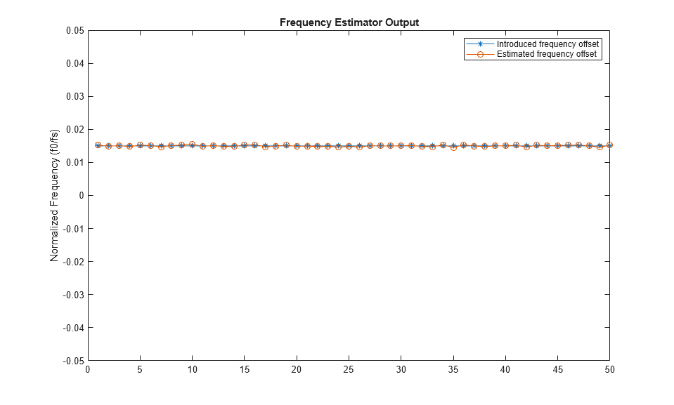
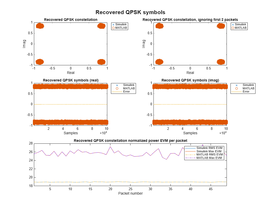
Frequency Offset Estimation for QPSK Modulated Signals
Estimate CFO for QPSK-modulated signals.
- Since R2026a
- Open Script
QPSK Transmitter and Receiver
Design and verify a QPSK transmitter and receiver for hardware.
- Since R2026a
- Open Script
Ports
Input
Input data, specified as a complex-valued scalar.
For correlation-based implementation, the input length must be equal to the averaging length. For FFT-based implementation, the input length must be equal to the FFT length.
The block supports double and single data
types for simulation but not for HDL code generation. For HDL code generation, the
block supports signed fixed point data type and the word length
must be in the range 8 to 32 and the fraction length must be less than or equal to
word length – 2.
Data Types: single | double | int8 | int16 | int32 | fixed point
Complex Number Support: Yes
Signal to indicate valid input data, specified as a Boolean
scalar.
The control signal at this port indicates when samples from the
data and refData input ports are valid.
When the value at this port is 1, the block captures the values on
the data and refData input ports. When the
value at the port is 0, the block ignores the values on the
data and refData input ports.
Data Types: Boolean
Reference data, specified as a real or a complex-valued scalar.
The block supports double and single data
types for simulation but not for HDL code generation. For HDL code generation, the
block supports signed fixed point data type and the word length
must be in the range 8 to 32 and the fraction length must be less than or equal to
word length – 2.
Dependencies
To enable this port, set the Modulation removal parameter
to Data aided.
Data Types: single | double | int8 | int16 | int32 | fixed point
Complex Number Support: Yes
Signal to clear internal states, specified as a Boolean scalar.
When this value is 1, the block stops the current calculation and
clears all internal states.
Dependencies
To enable this port, select the Enable reset input port parameter.
Data Types: Boolean
Output
Estimated frequency offset normalized by input sample rate, returned as a real-valued scalar.
Correlation-based Implementation
In correlation-based implementation, the output data type is same as the input
data for double and single data types. For the
fixed point data type, the output data type is
fixdt(1,WL,WL), where WL is the word length.
For the non-data aided method, WL is equal to
nextpow2(N) +nextpow2(M) + (2 x RWL) + 3, where:M is the modulation order.
N is the correlation length.
RWL is the modulation removed symbol word length. For this block, RWL value is fixed at 8.
For the data aided method, WL is equal to
nextpow2(N) + (2 x RWL) + 3.
FFT-based Implementation
In the FFT-based implementation, the output data type is the same as the input
data for double and single data types. For the
fixed point data type, the output data type is
fixdt(1,WL,WL).
For the non-data aided method, WL is equal to
nextpow2(FFTLength) +nextpow2(M), where:FFTLength is the FFT length.
M is the modulation order.
For the data aided method, WL is equal to
nextpow2(FFTLength).
Data Types: single | double | int16 | int32 | fixed point
Signal to indicate valid output data, returned as a Boolean
scalar.
The control signal at this port indicates when the data at the
freqEst output port is valid. When estimated samples are
available at the freqEst output port, the block sets the value at
this port to 1.
Data Types: Boolean
Parameters
Select the estimation algorithm to estimate the frequency offset from one of these options:
Correlation-based— Use the differential detection and averaging for estimation.FFT-based— Use the fast Fourier transform (FFT) for frequency estimation.
For more information, see Algorithms.
Specify the correlation length as a positive integer in the range 1 to 63.
Dependencies
To enable this parameter, set the Estimation algorithm
parameter to Correlation-based.
Specify the FFT length as of power of 2 in the range 4 to 65,536.
Dependencies
To enable this parameter, set the Estimation algorithm
parameter to FFT-based.
Specify the averaging length as a positive integer less than or equal to 65,536 and
greater than the correlation length. The averaging length must be less than or equal to
the length of the continuous sequence of known reference symbols when you select the
Data aided method.
Dependencies
To enable this parameter, set the Estimation algorithm
parameter to Correlation-based.
Select one of these modulation removal methods:
Non-data aided— Use this method when you know only the modulation type of the input data. Select the desired modulation type using the Modulation parameter.Data aided— Use this method when you already know the modulated symbols of the input data. Provide the known modulated symbols through the refData input port.
Select the modulation type as one of the following:
BPSK— Binary phase shift keyingQPSK— Quadrature phase shift keying8-PSK— 8-phase shift keying
Dependencies
To enable this parameter, set the Modulation removal
parameter to Non-data aided.
Select this parameter to enable the reset input port.
Algorithms
The Frequency Estimator block is designed to estimate the CFO of an observed signal. The block supports FFT-based and correlation-based algorithms to support different requirements.
The observed signal, cn, is represented as
For the data aided method xn is the known reference symbols such that the magnitude of xn is constant, and for the non-data aided method, xn is the modulated symbols.
-
where f0 is the carrier frequency offset and fs is the sampling frequency of the observed sequence.
θ is an unknown constant phase offset.
P is considered the averaging length for the correlation-based algorithm and as FFT length for the FFT-based algorithm.
The modulation removed symbol
For the data aided method,
and for the non-data aided method,
Where, ø is quantized with the phase quantization word length fixed at 8 and wrapped to lie within the range -π to π.
This section describes the correlation-based estimation algorithm used to estimate the frequency offset. The estimated frequency offset is calculated as:
where:
For data aided cases
For non-data aided cases
The estimation range is
where M is the modulation order, N is the correlation length, and L is the averaging length. For data aided cases, M is equal to 1.
This section describes the FFT-based estimation of frequency offsets. In FFT-based estimation, the spectrum of the sequence rn is divided into frequency bins. The edges of these bins represent the potential estimates of the algorithm. The actual estimate is the edge nearest to the frequency offset in the observed sequence.
The estimation range is
where M is the modulation order. For data aided cases, M is equal to 1.
The latency of the block varies with the estimation algorithm and modulation removal.
For the Correlation-based implementation, the latency also depends on
the input word length.
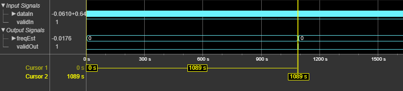
This figure shows a sample output of the block with input word length
16 and with default configuration. The latency of the block is 1089
clock cycles.

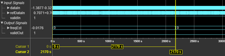
This figure shows a sample output of the block when you set the Estimation
algorithm parameter to FFT-based, FFT
length to 1024, Modulation removal
parameter to Data aided, and the Modulation
parameter to QPSK. The latency of the block is 2170 clock
cycles.

This table shows the resource and performance data synthesis results of the block for
the default configuration when you set the Estimation algorithm
parameter to Correlation-based, Correlation
length parameter to 4, Averaging length
parameter to 1024, Modulation removal parameter to
Non-data aided, and Modulation parameter
to QPSK. The input data provided is of type
fixdt(1,16,14). The generated HDL targets to the AMD®
Zynq®
UltraScale+™ MPSoC - ZCU102 Evaluation Board. The design achieves a clock frequency of
474.16 MHz.
| CLB LUTs | CLB Registers | DSPs | Block RAMs |
|---|---|---|---|
| 3355 | 4029 | 9 | 0 |
References
[1] Mengali, Umberto, and Aldo N. D’Andrea. Synchronization Techniques for Digital Receivers. Springer US, 1997. https://doi.org/10.1007/978-1-4899-1807-9.
[2] Luise, M., and R. Reggiannini. “Carrier Frequency Recovery in All-Digital Modems for Burst-Mode Transmissions.” IEEE® Transactions on Communications 43, no. 2/3/4 (Feb. 1995): 1169–78.
Extended Capabilities
This block supports C/C++ code generation for Simulink® accelerator and rapid accelerator modes and for DPI component generation.
HDL Coder provides additional configuration options that affect HDL implementation and synthesized logic.
This block has one default HDL architecture.
| ConstrainedOutputPipeline | Number of registers to place at
the outputs by moving existing delays within your design. Distributed
pipelining does not redistribute these registers. The default is
|
| InputPipeline | Number of input pipeline stages
to insert in the generated code. Distributed pipelining and constrained
output pipelining can move these registers. The default is
|
| OutputPipeline | Number of output pipeline stages
to insert in the generated code. Distributed pipelining and constrained
output pipelining can move these registers. The default is
|
| SynthesisAttributes |
Specifies the synthesis attributes for the blocks and block output signals in the model. The generated HDL code contains these attributes. For more information, see SynthesisAttributes (HDL Coder). |
You cannot generate HDL for this block inside a Resettable Synchronous Subsystem (HDL Coder).
Version History
Introduced in R2026a
MATLAB Command
You clicked a link that corresponds to this MATLAB command:
Run the command by entering it in the MATLAB Command Window. Web browsers do not support MATLAB commands.
选择网站
选择网站以获取翻译的可用内容,以及查看当地活动和优惠。根据您的位置,我们建议您选择:。
您也可以从以下列表中选择网站:
如何获得最佳网站性能
选择中国网站(中文或英文)以获得最佳网站性能。其他 MathWorks 国家/地区网站并未针对您所在位置的访问进行优化。
美洲
- América Latina (Español)
- Canada (English)
- United States (English)
欧洲
- Belgium (English)
- Denmark (English)
- Deutschland (Deutsch)
- España (Español)
- Finland (English)
- France (Français)
- Ireland (English)
- Italia (Italiano)
- Luxembourg (English)
- Netherlands (English)
- Norway (English)
- Österreich (Deutsch)
- Portugal (English)
- Sweden (English)
- Switzerland
- United Kingdom (English)

