expand all
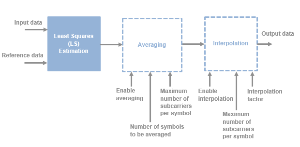
This figure shows the architecture block diagram of the OFDM Channel
Estimator block. The block implements least squares (LS) estimation for the channel
estimation. To improve the accuracy of LS estimation, the block uses an averaging technique
and provides an interpolation feature if the number of known reference signals are limited to
certain subcarriers for a particular OFDM symbol. The Least Squares (LS) Estimation block
calculates the least-squares estimates using the input data and the reference data.
The Averaging and Interpolation blocks are optional. To perform averaging, select the
Enable averaging parameter. To perform interpolation, select the
Enable interpolation parameter. The parameters shown in this figure
configure the behavior of the block.
The Averaging block accepts the LS estimates and averages the corresponding subcarriers
with valid LS estimates over the number of OFDM symbols to be averaged provided in the block
mask. This figure shows a sample output of the OFDM Channel Estimator block
when only averaging is enabled. In this case, the Number of symbols to be
averaged parameter is set to 4
, Maximum number of
subcarriers per symbol parameter is set to 16
, and the
numScPerSym port is set to 4
.
The block samples the numScPerSym port value at the first valid clock
cycle. After that, the block samples this value at the every first valid clock cycle, after
completing the valid number of Number of symbols to be averaged x
numScPerSym clock cycles. As the number of OFDM symbols to be averaged
is 4, the output valid shows the valid channel estimates obtained by averaging over four OFDM
symbols.
The Interpolation block accepts the LS estimates and performs linear interpolation to
calculate the missing channel information between two consecutive valid LS estimates. This
figure shows a sample output of the OFDM Channel Estimator block when only
interpolation is enabled. In this case, the Interpolation factor
parameter is set to 2
, Maximum number of subcarriers per
symbol parameter is set to 16
, and the
numScPerSym port is set to 8
.
The block samples the numScPerSym port value at the first valid clock
cycle. After that, the block samples this value at the every first valid clock cycle, after
completing the valid number of subcarriers per symbol clock cycles. The output valid shows
the interpolated LS estimates for two OFDM symbols.
Latency
The latency of the block varies with the block parameter values and
numScPerSym port values. This table provides the latency calculations
of the block for different conditions.
Enable Averaging Value | Enable Interpolation Value | Latency Value (in Clock Cycles) |
---|
Off | Off | 12 |
On | Off | [(Number of symbols to be averaged – 1) x
numScPerSym] + 13 |
Off | On | Interpolation factor + 11 |
On | On | [(Number of symbols to be averaged – 1) x
numScPerSym] + Interpolation factor +
12 |
This figure shows a sample output of the OFDM Channel Estimator block in
an LTE standard configuration. In this case, the Number of symbols to be
averaged parameter is set to 14
, Interpolation
factor parameter is set to 3
, Maximum number of
subcarriers per symbol parameter is set to 72
, and
numScPerSym port is set to 72
. The latency of the
block is 951 clock cycles.
Performance
This table shows the resource and performance data synthesis results of the block when
you set the Number of symbols to be averaged parameter to
14
, Interpolation factor parameter to
3
, Maximum number of subcarriers per symbol
parameter to 180
, and numScPerSym port to
180
. The input data provided is of data type
fixdt(1,16,13)
. The generated HDL is targeted to the AMD®
Zynq®- 7000 ZC706 evaluation board. The design achieves a clock frequency of 227.84
MHz.
Resource | Number Used |
---|
Slice LUTs | 845 |
Slice Registers | 782 |
DSPs | 12 |
Block RAMs | 1.5 |