Room Acoustic Beamforming Using Relative Transfer Functions
R2026bThis example shows how to use an adaptive beamformer with Relative Transfer Functions (RTFs) to extract a target speaker's signal from a multi-microphone recording in the presence of an interfering speaker and room reverberation.
In conference and smart-speaker applications, microphone arrays capture audio from all directions simultaneously. A beamformer uses the spatial information across microphones to enhance the signal from a desired direction while suppressing interference from other directions. Unlike free-field steering vectors that assume direct-path propagation only, RTFs capture the full acoustic channel between a source and the array, including room reflections. This makes RTF-based beamforming more robust in reverberant environments.
This example demonstrates:
Simulating a reverberant room with a target speaker and interferer
Computing Relative Transfer Functions from room impulse responses
Applying a Minimum Variance Distortionless Response (MVDR) or a Linearly Constrained Minimum Variance (LCMV) beamformer in the short-time Fourier transform (STFT) domain
Enhancing the output with a Wiener post-filter
Evaluating speech quality using objective measures
Define the Acoustic Scenario
Create a room and place a microphone array, a target speaker, and an interfering speaker at specified positions. Choose between a simple shoebox room or a realistic conference room modeled from an STL mesh. The helper functions that create room geometry also assign materials to the surfaces in the room. This allows the simulation to account for material absorption when computing the room impulse response.
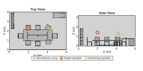
The microphone array is positioned on a desk surface, with the target speaker and interferer at different locations in the room.
% Set the random number generator for reproducibility of the results rng('default'); roomType ="Realistic"; switch roomType case "Shoebox" room = shoeboxRoom(); case "Realistic" room = realisticRoom(); otherwise error("Unsupported room type") end arrayPosition = [3; 1.5; 0.6]; speakerPosition = [2; 2.25; 1.4]; interfererPosition = [4.2; 2.25; 1.3];
Configure the Microphone Array
Select the array geometry. Two configurations are available:
Circular — 7 microphones arranged with one element at the center and six uniformly spaced on a 4.2 cm radius circle, matching the layout of devices like the Amazon Echo (1st generation). Circular arrays provide uniform spatial resolution in all azimuth directions, making them well-suited for conference speakerphones where the talker direction is unknown.
Linear — 8 microphones in a uniform linear array with a 280 mm aperture, similar to the Microsoft Surface Hub. Linear arrays offer higher resolution along their broadside axis but have front-back ambiguity and reduced performance for sources at endfire.
arrayGeometry ="Circular"; switch arrayGeometry case "Circular" % Amazon Echo (1st gen): 7 mics, ~4.2 cm radius numElements = 7; elementPositions = zeros(3, numElements); R = 0.042; dang = 360/(numElements-1); idx = (1:numElements-1)-1; x = cosd(idx*dang)*R; y = sind(idx*dang)*R; elementPositions(1, 2:end) = x; elementPositions(2, 2:end) = y; case "Linear" % Microsoft Surface Hub: 8 mics, uniform linear array with ~280 mm % aperture numElements = 8; elementPositions = zeros(3, numElements); apertureSize = 0.28; d = apertureSize/(numElements-1); elementPositions(2, :) = (0:numElements-1)*d - apertureSize/2; otherwise error("Unsupported array geometry"); end microphonePositions = arrayPosition + elementPositions;
Visualize the room layout showing the positions of the microphone array, target speaker, and interfering speaker.
viewRoom(room, microphonePositions, speakerPosition, interfererPosition);
Load Audio Signals
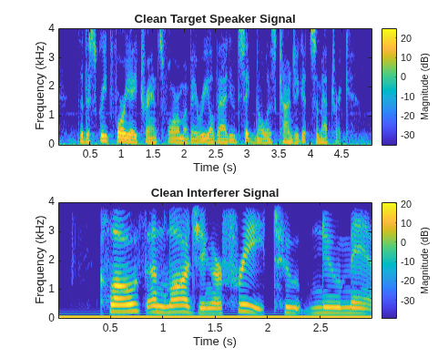
Load the target speech signal and the interfering speech signal. Both are single-channel recordings sampled at 8 kHz. Define STFT parameters that will be used throughout the example.
[speakerSignal, sampleRate] = audioread('SpeechDFT-16-8-mono-5secs.wav');
interfererSignal = audioread('FemaleSpeech-16-8-mono-3secs.wav');
In a conference room setting, the speaker of interest is typically louder than the interfering speaker. Adjust the interferer volume relative to the target speaker. Set to zero to isolate the effect of reverberation and sensor noise on beamformer performance.
interfererVolume =  0.8;
interfererSignal = interfererSignal*interfererVolume;
0.8;
interfererSignal = interfererSignal*interfererVolume;In this example speech signals are processed in the short-time Fourier transform (STFT) domain. Select STFT parameters.
windowLength = 128;
window = hann(windowLength, 'periodic');
overlapLength = 3*windowLength/4;
fftLength = 256;
Check if the selected STFT parameters satisfy the constant overlap-add (COLA) condition needed for perfect ISTFT reconstruction.
iscola(window, overlapLength)
ans = logical
   1
Visualize the spectrograms of the clean target and interfering signals before room propagation.
figure(Units='normalized', Position=[0.1 0.1 0.4 0.4]);
tiledlayout(2, 1);

nexttile;
stft(speakerSignal, sampleRate, Window=window, OverlapLength=overlapLength, FFTLength=fftLength);
ylim([0 1e-3*sampleRate/2]);
title('Clean Target Speaker Signal');

nexttile;
stft(interfererSignal, sampleRate, Window=window, OverlapLength=overlapLength, FFTLength=fftLength);
ylim([0 1e-3*sampleRate/2]);
title('Clean Interferer Signal');
Simulate Room Impulse Responses
Use acousticRoomResponse to compute the room impulse response (RIR) from each source to each microphone in the array. The RIR captures the direct path and all reflections from the room surfaces. The image source method models specular reflections up to the specified order, with material absorption applied at each reflection.
This example assumes omnidirectional microphones. To account for directional microphone patterns, the angle of arrival for each reflection component would need to be known so that the corresponding directivity gain can be applied to each path in the impulse response.
switch roomType
    case "Shoebox"
        r = room.Dimensions;
        imageSourceOrder = 3;
    case "Realistic"
        r = room.TriangulationObject;
        imageSourceOrder = 2;
end

maxNumRayReflections = 10;
numStochasticRays = 2000;

airSpeaker = acousticRoomResponse(r, speakerPosition.', microphonePositions.',...
    BandCenterFrequencies=room.CenterFrequencies, MaterialScattering=room.MaterialScattering,...
    SampleRate=sampleRate, MaterialAbsorption=room.MaterialAbsorption, ImageSourceOrder=imageSourceOrder,...
    MaxNumRayReflections=maxNumRayReflections, NumStochasticRays=numStochasticRays);

airInterferer = acousticRoomResponse(r, interfererPosition.', microphonePositions.',...
    BandCenterFrequencies=room.CenterFrequencies, MaterialScattering=room.MaterialScattering,...
    SampleRate=sampleRate, MaterialAbsorption=room.MaterialAbsorption, ImageSourceOrder=imageSourceOrder,...
    MaxNumRayReflections=maxNumRayReflections, NumStochasticRays=numStochasticRays);


airSpeaker = airSpeaker.';
airInterferer = airInterferer.';

% Zero-pad to equal length
responseLength = max(size(airSpeaker, 1), size(airInterferer, 1));
airSpeaker = paddata(airSpeaker, responseLength);
airInterferer = paddata(airInterferer, responseLength);
Plot the room impulse responses at the first microphone for both the target speaker and the interferer.
% Sound wave propagation speed (m/s)
propagationSpeed = 343;
t = (0:responseLength-1)/sampleRate;

figure(Units='normalized', Position=[0.1 0.1 0.4 0.4]);
tiledlayout(2, 1);

nexttile;
plot(t*1e3, airSpeaker(:, 1));
xlim([0 80]);
grid on;
xlabel('Time (ms)');
title('Room Impulse Response at Microphone 1 — Target Speaker');

nexttile;
plot(t*1e3, airInterferer(:, 1));
xlim([0 80]);
grid on;
xlabel('Time (ms)');
title('Room Impulse Response at Microphone 1 — Interferer');
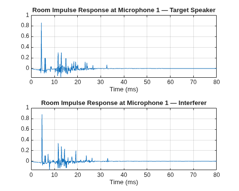
Note that the acoustic room response depends on the location of the source. This example assumes that the target speaker and the interferer positions are perfectly known. In practice these positions would need to be estimated first.
Compute Relative Transfer Functions
The Relative Transfer Function (RTF) characterizes the spatial signature of a source relative to a reference microphone. Unlike a simple steering vector that only encodes the direct-path phase difference, the RTF includes the effect of room reflections across all frequencies.
The RTF is computed by taking the ratio of the Acoustic Transfer Function (ATF) at each microphone to the ATF at the reference microphone. This normalization ensures unity gain at the reference and preserves the relative magnitude and phase relationships across the array.
Two normalization options are supported:
"Reference Mic"— Standard RTF definition: ATF divided by the reference microphone ATF. Preserves the signal as heard at the reference microphone."Unit Norm"— Normalize to unit L2 norm and remove reference phase. Applies frequency-dependent whitening to the output.
rtfNormalization ="Reference Mic"; referenceMicIndex = 1; % RTF for the target speaker [atfSpeaker, rtfFrequencies] = air2atf(airSpeaker, sampleRate); switch rtfNormalization case "Unit Norm" rtfSpeaker = atfSpeaker./vecnorm(atfSpeaker, 2, 2); rtfSpeaker = rtfSpeaker .* exp(-1j*angle(rtfSpeaker(:, referenceMicIndex))); case "Reference Mic" rtfSpeaker = atfSpeaker./atfSpeaker(:, referenceMicIndex); otherwise error("Unsupported RTF normalization: %s", rtfNormalization); end % RTF for the interferer atfInterferer = air2atf(airInterferer, sampleRate); switch rtfNormalization case "Unit Norm" rtfInterferer = atfInterferer./vecnorm(atfInterferer, 2, 2); rtfInterferer = rtfInterferer .* exp(-1j*angle(rtfInterferer(:, referenceMicIndex))); case "Reference Mic" rtfInterferer = atfInterferer./atfInterferer(:, referenceMicIndex); otherwise error("Unsupported RTF normalization: %s", rtfNormalization); end
Simulate the Received Signal
Simulate the multi-channel signal received at the microphone array by filtering each clean source signal through its corresponding room impulse response using fftfilt, which performs efficient overlap-add convolution in the frequency domain. Add spatially white Gaussian noise to model sensor self-noise at a specified SNR relative to the target speaker power at the reference microphone.
receivedSpeakerSignal = fftfilt(airSpeaker, speakerSignal);

signalLength = max(numel(speakerSignal), numel(interfererSignal));
receivedSignal = zeros(signalLength + responseLength - 1, numElements);
receivedSignalNoSpeaker = zeros(size(receivedSignal));

idxs = 1:size(receivedSpeakerSignal, 1);
receivedSignal(idxs, :) = receivedSignal(idxs, :) + receivedSpeakerSignal;
receivedInterfererSignal = fftfilt(airInterferer, interfererSignal);

idxs = 1:size(receivedInterfererSignal, 1);
receivedSignal(idxs, :) = receivedSignal(idxs, :) + receivedInterfererSignal;
receivedSignalNoSpeaker(idxs, :) = receivedSignalNoSpeaker(idxs, :) + receivedInterfererSignal;
Set the sensor noise level. The SNR is defined relative to the target speaker power at the reference microphone. Lower values simulate noisier sensors, making the beamforming task more challenging.
targetSNR =18; % dB speakerPowerRef = mean(receivedSpeakerSignal(:, referenceMicIndex).^2); noiseVariance = speakerPowerRef / db2pow(targetSNR); receivedSignal = receivedSignal + sqrt(noiseVariance)*randn(size(receivedSignal)); receivedSignalNoSpeaker = receivedSignalNoSpeaker + sqrt(noiseVariance)*randn(size(receivedSignalNoSpeaker));
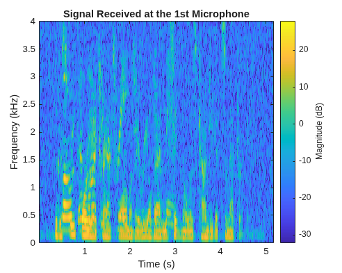
The spectrogram of the received signal at the first microphone shows the target speech mixed with the interferer and room reverberation.
figure(Units='normalized', Position=[0.1 0.1 0.4 0.4]);
stft(receivedSignal(:, 1), sampleRate, Window=window, OverlapLength=overlapLength, FFTLength=fftLength);
ylim([0 1e-3*sampleRate/2]);

title('Signal Received at the 1st Microphone');
Apply Beamforming and Post-Filter
To remove noise and interference, the received speech signal is processed in the STFT domain.
[stftSignal, stftFrequencies] = stft(receivedSignal, sampleRate, Window=window, OverlapLength=overlapLength, FFTLength=fftLength);
stftSignalNoSpeaker = stft(receivedSignalNoSpeaker, sampleRate, Window=window, OverlapLength=overlapLength, FFTLength=fftLength);

numTimeFrames = size(stftSignal, 2);
stftSignalBeamformed = zeros(fftLength, numTimeFrames);
stftSignalPostFiltered = zeros(fftLength, numTimeFrames);
At each frequency , the optimal broadband filter that jointly minimizes speech distortion and residual noise can be decomposed into a beamformer followed by a single-channel Wiener post-filter:
where is the beamformer weight vector computed from the RTF steering vector and the spatial covariance matrix , and , are the signal and noise power spectral densities at the beamformer output.
The covariance matrix is estimated using phased.CovarianceEstimator with shrinkage-based diagonal loading for numerical robustness.
covarianceEstimator = phased.CovarianceEstimator(DiagonalLoading="Shrinkage");Excluding the target speaker from the covariance estimate uses only the interference-plus-noise covariance, which prevents signal self-cancellation and yields optimal performance. In practice, obtaining a clean noise-only covariance requires a voice activity detector or a noise-only calibration period.
excludeTargetSpeakerFromCovariance =  true;
true;Choose between MVDR, which places a single distortionless constraint on the target direction, or LCMV, which additionally places a null constraint on the interferer direction. MVDR requires only the target speaker's RTF, while LCMV additionally requires the interferer's RTF to place an explicit null constraint.
beamformingWeights =  "LCMV";
Pick the forgetting factor for the Zelinski post-filter. Lower values weight the current frame more heavily, allowing faster tracking of non-stationary speech but with noisier gain estimates. Higher values produce smoother gain estimates at the cost of temporal smearing.
alpha =  0.15;
0.15;Loop over frequency bins to compute beamformer weights and apply the Zelinski post-filter at each subband.
% Loop over subbands
for i = 1:fftLength
    subbandSignal = squeeze(stftSignal(i, :, :));

    % Compute covariance matrix
    if excludeTargetSpeakerFromCovariance
        subbandSignalNoSpeaker = squeeze(stftSignalNoSpeaker(i, :, :));
        cov = covarianceEstimator(subbandSignalNoSpeaker);
    else
        cov = covarianceEstimator(subbandSignal);
    end

    [~, idx] = min(abs(rtfFrequencies-stftFrequencies(i)));

    % RTF of the speaker and the interferer at this subband
    vSpeaker = rtfSpeaker(idx, :).';
    vInterferer = rtfInterferer(idx, :).';

    switch beamformingWeights
        case "MVDR"
            % Calling lcmvweights with a single constraint (distortionless
            % speaker signal) results in MVDR weights
            w = lcmvweights(vSpeaker, 1, cov);
        case "LCMV"
            w = lcmvweights([vSpeaker vInterferer], [1; 0], cov);
        otherwise
            error("Unsupported beamforming algorithm");
    end

    % Apply beamforming
    stftSignalBeamformed(i, :) = w'*subbandSignal.';

    % Apply single channel Wiener filter
    h = zelinskiPostFilter(subbandSignal, alpha, vSpeaker);
    stftSignalPostFiltered(i, :) = stftSignalBeamformed(i, :).*h;
end
Reconstruct Time-Domain Signals
Convert the beamformed and post-filtered STFT signals back to the time domain using the inverse STFT.
receivedSignalBeamformed = istft(stftSignalBeamformed, sampleRate, Window=window,...
    OverlapLength=overlapLength, FFTLength=fftLength, ConjugateSymmetric=true);

receivedSignalPostFiltered = istft(stftSignalPostFiltered, sampleRate, Window=window,...
    OverlapLength=overlapLength, FFTLength=fftLength, ConjugateSymmetric=true);
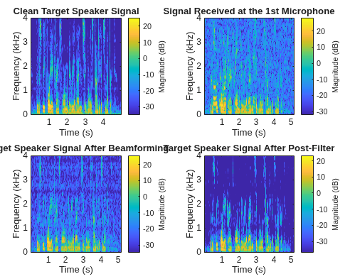
Compare the spectrograms of the clean target signal, the received mixture at the first microphone, the beamformer output, and the post-filtered output. The beamformed signal shows significant suppression of the interferer while preserving the target speech structure. The post-filter further reduces residual noise visible as diffuse energy between speech harmonics.
figure(Units='normalized', Position=[0.1 0.1 0.4 0.4]);
tiledlayout(2, 2, TileSpacing="compact", Padding="compact");

nexttile;
stft(speakerSignal, sampleRate, Window=window, OverlapLength=overlapLength, FFTLength=fftLength);
ylim([0 1e-3*sampleRate/2]);
title('Clean Target Speaker Signal');

nexttile;
stft(receivedSignal(:, 1), sampleRate, Window=window, OverlapLength=overlapLength, FFTLength=fftLength);
ylim([0 1e-3*sampleRate/2]);
title('Signal Received at the 1st Microphone');

nexttile;
stft(receivedSignalBeamformed, sampleRate, Window=window, OverlapLength=overlapLength, FFTLength=fftLength);
ylim([0 1e-3*sampleRate/2]);
title('Target Speaker Signal After Beamforming');

nexttile;
stft(receivedSignalPostFiltered, sampleRate, Window=window, OverlapLength=overlapLength, FFTLength=fftLength);
ylim([0 1e-3*sampleRate/2]);
title('Target Speaker Signal After Post-Filter');
Evaluate Speech Quality
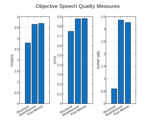
Quantify the improvement using objective speech quality measures:
ViSQOL — Virtual Speech Quality Objective Listener, a perceptual quality metric. Higher values indicate better quality (scale 1–5).
STOI — Short-Time Objective Intelligibility. Higher values indicate better intelligibility (scale 0–1).
SISNR — Scale-invariant signal-to-noise ratio. Measures waveform fidelity by comparing the processed signal sample-by-sample to the reference.
ViSQOL and STOI are perceptual metrics that model human hearing, while SI-SNR is a waveform metric. The post-filter may improve perceptual quality while reducing SI-SNR, because it attenuates low-energy content between speech harmonics that is inaudible but technically part of the reference waveform.
Compare three signals against the clean target: the raw received signal at the first microphone, the beamformer output, and the post-filtered output.
% To better align the reference and the processed signals prepend the
% reference signal with zeros corresponding to the propagation delay
speakerToMicDelay = round(sampleRate*norm(speakerPosition - arrayPosition)/propagationSpeed);
speakerSignalWithDelay = paddata(speakerSignal, numel(speakerSignal)+speakerToMicDelay, Side="leading");

[visqolReceived, stoiReceived, sisnrReceived] = computeObjectiveMetrics(...
    receivedSignal(:, 1), speakerSignalWithDelay, sampleRate, windowLength);

[visqolBeamformed, stoiBeamformed, sisnrBeamformed] = computeObjectiveMetrics(...
    receivedSignalBeamformed, speakerSignalWithDelay, sampleRate, windowLength);

[visqolPostFiltered, stoiPostFiltered, sisnrPostFiltered] = computeObjectiveMetrics(...
    receivedSignalPostFiltered, speakerSignalWithDelay, sampleRate, windowLength);
Visualize the quality metrics as grouped bar charts.
figure(Units='normalized', Position=[0.1 0.1 0.4 0.4]);
tiledlayout(1, 3);

nexttile;
visqolResults = [visqolReceived; visqolBeamformed; visqolPostFiltered];
bar(visqolResults);
xticklabels({'Received', 'Beamformed', 'Post-filtered'});
ylabel('ViSQOL');
grid on;

nexttile;
stoiResults = [stoiReceived; stoiBeamformed; stoiPostFiltered];
bar(stoiResults);
xticklabels({'Received', 'Beamformed', 'Post-filtered'});
ylabel('STOI');
grid on;

nexttile;
sisnrResults = [sisnrReceived; sisnrBeamformed; sisnrPostFiltered];
bar(sisnrResults);
xticklabels({'Received', 'Beamformed', 'Post-filtered'});
ylabel('SISNR (dB)');
grid on;

sgtitle('Objective Speech Quality Measures');
Listen to the Results
Play back the clean target signal, the noisy received mixture at the first microphone, and the enhanced post-filtered output. This allows you to hear the progressive improvement from raw capture to beamformed and post-filtered output.
% Clean target speaker
sound(speakerSignal, sampleRate);
pause(length(speakerSignal)/sampleRate + 0.5);

% Received signal at microphone 1 (target + interferer + noise)
sound(receivedSignal(:,1), sampleRate);
pause(size(receivedSignal,1)/sampleRate + 0.5);

% After beamforming only
sound(receivedSignalBeamformed, sampleRate);
pause(size(receivedSignal,1)/sampleRate + 0.5);

% After beamforming and post-filtering
sound(receivedSignalPostFiltered, sampleRate);
Summary
This example demonstrated RTF-based acoustic beamforming for speech enhancement in a reverberant environment. The key insight is that Relative Transfer Functions capture the full acoustic path between source and array — including room reflections — enabling more effective spatial filtering than free-field steering vectors alone.
The beamformer suppresses the interfering speaker spatially, while the Wiener post-filter provides additional single-channel noise reduction by estimating the signal-to-noise ratio from inter-microphone cross-spectral correlations. Together, these stages progressively improve both perceptual quality and intelligibility relative to the raw microphone signal.
Use the interactive controls to explore how different configurations affect performance:
Room geometry and reverberation level
Array topology (circular vs. linear)
Beamformer type (MVDR vs. LCMV)
RTF normalization method
Post-filter forgetting factor
Supporting Functions
function [v, s, snr] = computeObjectiveMetrics(processedSignal, referenceSignal, sampleRate, windowLength)
    % Compute ViSQOL, STOI, and SISNR metrics

    [processedSignalAligned, referenceSignalAligned] = alignsignals(processedSignal, referenceSignal);
    v = visqol(processedSignalAligned, referenceSignalAligned, sampleRate, Mode="speech");

    len = min(numel(processedSignalAligned), numel(referenceSignalAligned));
    s = stoi(processedSignalAligned(1:len), referenceSignalAligned(1:len), sampleRate);

    % Skip first windowLength samples to remove impact of transients
    snr = sisnr(processedSignalAligned(1+windowLength:len), referenceSignalAligned(1+windowLength:len), SubtractMean=true);
end

function room = shoeboxRoom()
    % Shoebox room parameters including room dimensions and the definition
    % of the absorption materials for walls, floor, and ceiling

    room = struct( ...
        Dimensions = [6, 4, 3.25], ...
        CenterFrequencies = [125, 250, 500, 1000, 2000, 4000], ...
        MaterialAbsorption = [ ...
        "CarpetOnConcrete"        % floor
        "GypsumBoard"             % front
        "GypsumBoard"             % back
        "GypsumBoard"             % left
        "GypsumBoard"             % right
        "OwensCorningDropCeiling" % ceiling
        ], ...
        MaterialScattering = "high", ...
        Description = 'Shoebox Room'...
        );
end

function room = realisticRoom()
    % Load a conference room from an .stl file and assign materials to the
    % walls, floor, ceiling, and furniture

    room.TriangulationObject = stlread("conference_room.stl");
    room.CenterFrequencies = [125, 250, 500, 1000, 2000, 4000];

    pts = room.TriangulationObject.Points;
    tris = room.TriangulationObject.ConnectivityList;
    cents = (pts(tris(:,1),:) + pts(tris(:,2),:) + pts(tris(:,3),:)) / 3;
    numFaces = size(tris, 1);

    xMin = min(pts(:,1)); xMax = max(pts(:,1));
    yMin = min(pts(:,2)); yMax = max(pts(:,2));
    zMax = max(pts(:,3));
    tol = 0.001;

    floorMask = cents(:,3) < tol;
    ceilingMask = cents(:,3) > zMax - tol;

    % Walls: faces on room boundary that are not floor or ceiling
    wallMask = (cents(:,1) < xMin + tol | cents(:,1) > xMax - tol | ...
        cents(:,2) < yMin + tol | cents(:,2) > yMax - tol) & ...
        ~floorMask & ~ceilingMask;

    % Assign materials
    materials = repmat("Hardwood", numFaces, 1);
    materials(floorMask) = "CarpetOnConcrete";
    materials(ceilingMask) = "OwensCorningDropCeiling";
    materials(wallMask) = "GypsumBoard";

    room.MaterialAbsorption = materials;
    room.MaterialScattering = "high";
    room.Description = 'Realistic Room';
end

function [atf, f] = air2atf(air, sampleRate)
    % Compute Acoustic Transfer Function from Acoustic Impulse Response

    dim = 1;
    N = size(air, dim);
    nFFT = 2^nextpow2(N);
    atf = fft(air, nFFT, dim);
    atf = fftshift(atf, dim);
    f = (0:nFFT-1)*sampleRate/nFFT - sampleRate/2;
end

function h = zelinskiPostFilter(x, alpha, v)
    % Zelinski post-filter

    [m, n] = size(x);

    xa = x(1,:)./v.'; % time aligned
    A = xa'*xa;
    h = zeros(1,m);
    h(1) = 2/(n-1) * sum(sum(triu(A,1)))/sum(diag(A));

    for i = 2:m
        xa = x(i,:)./v.';
        A = alpha * A + (1-alpha)*(xa'*xa);
        h(i) = 2/(n-1) * real(sum(sum(triu(A,1))))/sum(diag(A));
    end
end

function viewRoom(room, microphonePositions, speakerPosition, interfererPosition)
    if strcmp(room.Description, 'Realistic Room')
        viewRealisticRoom(room.TriangulationObject, microphonePositions, speakerPosition, interfererPosition)
    else
        viewShoeboxRoom(room.Dimensions, microphonePositions, speakerPosition, interfererPosition)
    end
end

function viewShoeboxRoom(roomDimensions, microphonePositions, speakerPosition, interfererPosition)
    % Display the shoebox room showing views from the top and from the
    % side

    roomLength = roomDimensions(1);
    roomWidth = roomDimensions(2);
    roomHeight = roomDimensions(3);

    figure(Units='normalized', Position=[0.1 0.1 0.4 0.25]);

    nRows = 2;
    tiledlayout(nRows, 2, TileSpacing="compact", Padding="compact");

    ax1 = nexttile([nRows 1]);
    hold(ax1, 'on');
    colors = ax1.ColorOrder;

    plot([0 roomLength], [0 0], Color = 'k', LineWidth = 1,...
        DisplayName = 'Room boundaries');
    plot([0 0], [0 roomWidth], Color = 'k', LineWidth = 1,...
        HandleVisibility="off");
    plot([0 roomLength], [roomWidth roomWidth], Color = 'k', LineWidth = 1,...
        HandleVisibility="off");
    plot([roomLength roomLength], [0 roomWidth], Color = 'k', LineWidth = 1,...
        HandleVisibility="off");

    plot(microphonePositions(1, :), microphonePositions(2, :), '.', Color = colors(1, :),...
        DisplayName = 'Microphone array', MarkerSize = 10, LineWidth = 2);
    plot(speakerPosition(1), speakerPosition(2), 'o', Color = colors(2, :),...
        DisplayName = 'Target speaker', MarkerSize = 8, LineWidth = 2);
    plot(interfererPosition(1), interfererPosition(2), 's', Color = colors(3, :),...
        DisplayName = 'Interfering speaker', MarkerSize = 8, LineWidth = 2);

    grid(ax1, 'on');
    xlabel(ax1, 'X (m)');
    ylabel(ax1, 'Y (m)');
    axis(ax1, 'equal');
    axis(ax1, 'tight');
    title(ax1, 'Top View');

    ax2 = nexttile([nRows 1]);
    hold(ax2, 'on');
    plot([0 roomLength], [0 0], Color = 'k', LineWidth = 1,...
        DisplayName = 'Room boundaries');
    plot([0 0], [0 roomHeight], Color = 'k', LineWidth = 1,...
        HandleVisibility="off");
    plot([0 roomLength], [roomHeight roomHeight], Color = 'k', LineWidth = 1,...
        HandleVisibility="off");
    plot([roomLength roomLength], [0 roomHeight], Color = 'k', LineWidth = 1,...
        HandleVisibility="off");

    plot(microphonePositions(1, :), microphonePositions(3, :), '.', Color = colors(1, :),...
        DisplayName = 'Microphone array', MarkerSize = 10, LineWidth = 2);
    plot(speakerPosition(1), speakerPosition(3), 'o', Color = colors(2, :),...
        DisplayName = 'Target speaker', MarkerSize = 8, LineWidth = 2);
    plot(interfererPosition(1), interfererPosition(3), 's', Color = colors(3, :),...
        DisplayName = 'Interfering speaker', MarkerSize = 8, LineWidth = 2);

    grid(ax2, 'on');
    xlabel(ax2, 'X (m)');
    ylabel(ax2, 'Z (m)');
    axis(ax2, 'equal');
    axis(ax2, 'tight');
    title(ax2, 'Side View');

    lgd = legend(NumColumns=4);
    lgd.Layout.Tile = 'south';
end

function viewRealisticRoom(triangulationObject, microphonePositions, speakerPosition, interfererPosition)
    % Display the realistic conference room showing views from the top and
    % from the side

    figure(Units='normalized', Position=[0.1 0.1 0.4 0.25]);

    nRows = 2;
    tiledlayout(nRows, 2, TileSpacing="compact", Padding="compact");

    ax1 = nexttile([nRows 1]);
    hold(ax1, 'on');
    colors = ax1.ColorOrder;

    trisurf(triangulationObject, FaceAlpha=0.2, FaceColor=[.5 .5 .5], EdgeColor="none", HandleVisibility='off');
    view(ax1, 0, 90);

    axis(ax1, 'equal');
    axis(ax1, 'tight');
    grid(ax1, 'off');

    xlabel(ax1, "X (m)");
    ylabel(ax1, "Y (m)");
    zlabel(ax1, "Z (m)");

    % Plot edges
    fe = featureEdges(triangulationObject,pi/20);
    numEdges = size(fe, 1);
    pts = triangulationObject.Points;
    a = pts(fe(:,1), :);
    b = pts(fe(:,2), :);
    fePts = cat(1, reshape(a,1,numEdges,3), reshape(b, 1, numEdges, 3), ...
        nan(1,numEdges,3));

    fePts = reshape(fePts, [], 3);
    plot3(fePts(:,1), fePts(:,2), fePts(:,3), "k", LineWidth=.5, HandleVisibility='off');

    plot3(microphonePositions(1, :), microphonePositions(2, :), microphonePositions(3, :),...
        '.', Color = colors(1, :), DisplayName = 'Microphone array', MarkerSize = 10, LineWidth = 2);
    plot3(speakerPosition(1), speakerPosition(2), speakerPosition(3), 'o', Color = colors(2, :),...
        DisplayName = 'Target speaker', MarkerSize = 8, LineWidth = 2);
    plot3(interfererPosition(1), interfererPosition(2), interfererPosition(3), 's', Color = colors(3, :),...
        DisplayName = 'Interfering speaker', MarkerSize = 8, LineWidth = 2);

    title(ax1, 'Top View');
    hold(ax1, 'off');

    ax2 = nexttile([nRows 1]);

    % Copy everything from ax1 into ax2
    copyobj(allchild(ax1), ax2);

    view(ax2, 0, 0);

    axis(ax2, 'equal');
    axis(ax2, 'tight');
    grid(ax2, 'off');

    xlabel(ax2, "X (m)");
    ylabel(ax2, "Y (m)");
    zlabel(ax2, "Z (m)");

    title(ax2, 'Side View');
    lgd = legend(NumColumns=3);
    lgd.Layout.Tile = 'south';
end
See Also
acousticRoomResponsedsp.FrequencyDomainFIRFilterlcmvweightsphased.CovarianceEstimatorsisnrstoivisqol

