apskdemod
Amplitude phase shift keying (APSK) demodulation
Description
Z = apskdemod(Y,M,radii)Y, based on the
specified number of constellation points per PSK ring, M, and
the radius of each PSK ring, radii. For a description of APSK
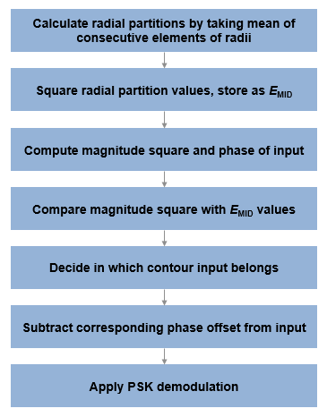
demodulation, see APSK Hard Demodulation and APSK Soft Demodulation.
Note
apskdemod specifically applies to multiple ring PSK
constellations. For a single ring PSK constellation, use pskdemod.
Z = apskdemod(Y,M,radii,phaseoffset)
Z = apskdemod(___,Name=Value)apskdemod(Y,M,PlotConstellation=true) demodulates using
constellation points per ring specified in input vector M and
plots the constellation. Specify name-value arguments after all other input
arguments.
Examples
Demodulate a 16-APSK signal that has an unequal number of constellation points on each circle. Plot the received constellation.
Define vectors for modulation order and PSK ring radii. Generate random 16-ary data symbols.
M = [4 12];
radii = [1 2];
modOrder = sum(M);

x = randi([0 modOrder-1],1000,1);
Apply APSK modulation to the data.
txSig = apskmod(x,M,radii);
Pass the modulated signal through a noisy channel.
snr = 20; % dB
rxSig = awgn(txSig,snr,'measured');
Plot the transmitted (reference) signal points and the noisy received signal points.
plot(rxSig,'b*')
hold on
grid
plot(txSig,'r+')
xlim([-3 3])
ylim([-3 3])
xlabel('In-Phase')
ylabel('Quadrature')
legend('Received constellation','Reference constellation')

Demodulate the received signal and compare to the input data.
z = apskdemod(rxSig,M,radii);
isequal(x,z)
ans = logical
   0
Demodulate a 64-APSK signal with custom symbol mapping. Compute hard decision bit output and verify that the input matches the output.
Define vectors for modulation order and PSK ring radii. Generate 100 symbols of random bit input.
M = [8 12 16 28]; % 4-PSK circles
modOrder = sum(M);
radii = [0.5 1 1.3 2];
x = randi([0 1],100*log2(modOrder),1);
Create a custom symbol mapping vector of binary mapping.
cmap = 0:63;
Modulate the data and plot the constellation.
y = apskmod(x,M,radii, ...
        SymbolMapping=cmap, ...
        InputType='bit', ...
        PlotConstellation=true);

Demodulate the received signal.
z = apskdemod(y,M,radii,SymbolMapping=cmap,OutputType='bit');Verify that the demodulated signal is equal to the original data.
isequal(x,z)
ans = logical
   1
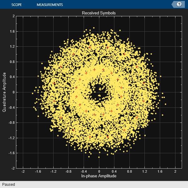
Demodulate a 32-APSK signal and calculate soft bits.
Define vectors for modulation order and PSK ring radii. Generate 10000 symbols of random bit data.
M = [16 16];
modOrder = sum(M);
radii = [0.6 1.2];
numSym = 10000;
x = randi([0 1], numSym*log2(modOrder),1);
Generate a reference constellation. Create a constellation diagram object.
refAPSK = apskmod(0:modOrder-1,M,radii);
constDiagAPSK = comm.ConstellationDiagram( ...
    ReferenceConstellation=refAPSK, ...
    Title='Received Symbols', ...
    XLimits=[-2 2], ...
    YLimits=[-2 2]);
Modulate the data.
txSig = apskmod(x,M,radii,InputType='bit');
sigPow = var(txSig);
Pass the signal through a noisy channel.
snr = 15;
rxSig = awgn(txSig,snr,sigPow,'linear');
Plot the reference and received constellation symbols.
constDiagAPSK(rxSig)

Demodulate the signal and compute soft bits.
z = apskdemod(rxSig,M,radii, ...
    OutputType='approxllr', ...
    NoiseVariance=sigPow/snr);
Input Arguments
APSK modulated signal, specified as a complex scalar, vector, or matrix.
When Y is a matrix, each column is treated as an
independent channel.
Data Types: double | single
Complex Number Support: Yes
Constellation points per PSK ring, specified as an integer vector with
more than one element. Vector elements indicate the number of constellation
points in each PSK ring. The first element corresponds to the innermost
circle, and so on, until the last element, that corresponds to the outermost
circle. Element values must be multiples of four and
sum( must be a power of
two. The modulation order is the total number of points in the signal
constellation and equals the sum of the vector elements,
M)sum(.M)
Example: [4 12 16] specifies a three PSK ring
constellation with a modulation order of sum(M) =
32.
Data Types: double
Radius per PSK ring, specified as a vector with the same length as
M. The first element corresponds to the innermost
circle, and so on, until the last element, that corresponds to the outermost
circle. The elements must be positive and arranged in increasing
order.
Example: [0.5 1 2] defines constellation PSK ring radii.
The inner ring has a radius of 0.5, the second ring has a radius of 1.0, and
the outer ring has a radius of 2.0.
Data Types: double
Phase offset of each PSK ring in radians, specified as a scalar or vector
with the same length as M. The first element
corresponds to the innermost circle, and so on, until the last element, that
corresponds to the outermost circle. The phaseoffset
can be a scalar only if all the elements of M are the
same value.
Example: [pi/4 pi/12 pi/16] defines three constellation
PSK ring phase offsets. The inner ring has a phase offset of pi/4, the
second ring has a phase offset of pi/12, and the outer ring has a phase
offset of pi/16.
Data Types: double
Name-Value Arguments
Specify optional pairs of arguments as
Name1=Value1,...,NameN=ValueN, where Name is
the argument name and Value is the corresponding value.
Name-value arguments must appear after other arguments, but the order of the
pairs does not matter.
Example: Z =
apskdemod(Y,M,radii,OutputType='bit',OutputDataType='single');
Symbol mapping, specified as one of the following:
'contourwise-gray'— Uses Gray mapping along the contour in phase dimension for each PSK ring.'gray'— Uses Gray mapping along the contour in both the amplitude and phase dimensions. For Gray symbol mapping, all the values forMmust be equal and all the values forphaseoffsetmust be equal. For a description of the Gray mapping used, see [2].integer vector — Use custom symbol mapping. Vector must consist of
sum(unique elements with values in the range [0, (M)sum(]. The first element corresponds to the constellation point in the first quadrant of the innermost circle, with subsequent elements positioned counterclockwise around the PSK rings.M)-1
The default symbol mapping depends on M and phaseoffset. When all the elements of
M and phaseOffset are
equal, the default is 'gray'. For all other cases,
the default is 'contourwise-gray'.
Data Types: double | char | string
Output type, specified as 'integer',
'bit', 'llr', or
'approxllr'. For a description of the returned
output, see Z.
Output data type, specified as one of the data types listed in this
table. Acceptable values for OutputDataType depend
on the OutputType value.
OutputType
Value | Acceptable
OutputDataType Values |
|---|---|
'integer' | 'double',
'single',
'int8',
'int16',
'int32',
'uint8',
'uint16', or
'uint32' |
'bit' | 'double',
'single',
'int8',
'int16',
'int32',
'uint8',
'uint16',
'uint32', or
'logical' |
The default value is the data type of input Y.
Dependencies
To enable this argument, set OutputType to
either 'integer' or
'bit'.
Noise variance, specified as one of these options:
Positive scalar — The function uses the same noise variance value on all input elements.
Vector of positive values — For all the elements of the input along the corresponding last dimension, the function uses the noise variance specified by each element of the vector. The vector length must be equal to the number of columns in the input signal.
When the noise variance or signal power result in computations involving extreme positive or negative magnitudes, see APSK Soft Demodulation for algorithm selection considerations.
Dependencies
This argument applies when you set OutputType to 'llr' or
'approxllr'.
Data Types: double
Option to plot constellation, specified as logical
0 (false) or
1 (true). To plot the
constellation, set PlotConstellation to
true.
Data Types: logical
Output Arguments
Demodulated signal, returned as a scalar, vector, or matrix. The value and
dimension of this output vary depending on the specified OutputType value, as shown in this table.
OutputType
Value | apskdemod Output
Value | Dimensions of Output |
|---|---|---|
'integer' | Demodulated integer values from 0 to
(sum(M) – 1) | Z has the same dimensions as input
Y. |
'bit' | Demodulated bits | The number of rows in Z
is log2(sum(M)) times the number of rows in
Y. Each demodulated symbol is mapped
to a group of log2(sum(M)) elements in a column, where the first
element represents the MSB and the last element represents
the LSB. |
'llr' | Log-likelihood ratio value for each bit | |
'approxllr' | Approximate log-likelihood ratio value for each bit |
Algorithms
For soft demodulation, two soft-decision log-likelihood ratio (LLR) algorithms are available: exact LLR and approximate LLR. The exact LLR algorithm is more accurate but has slower execution speed than the approximate LLR algorithm. For further description of these algorithms, see the Hard- vs. Soft-Decision Demodulation topic.
Note
The exact LLR algorithm computes exponentials using finite precision arithmetic. For computations involving very large positive or negative magnitudes, the exact LLR algorithm yields:
Infor-Infif the noise variance is a very large valueNaNif the noise variance and signal power are both very small values
The approximate LLR algorithm does not compute exponentials. You can avoid
Inf, -Inf, and NaN results by using
the approximate LLR algorithm.
References
[1] Sebesta, J. “Efficient Method for APSK Demodulation.” Selected Topics on Applied Mathematics, Circuits, Systems, and Signals (P. Pardalos, N. Mastorakis, V. Mladenov, and Z. Bojkovic, eds.). Vouliagmeni, Athens, Greece: WSEAS Press, 2009.
[2] Liu, Z., Q. Xie, K. Peng, and Z. Yang. "APSK Constellation with Gray Mapping." IEEE Communications Letters. Vol. 15, Number 12, December 2011, pp. 1271–1273.
Extended Capabilities
C/C++ Code Generation
Generate C and C++ code using MATLAB® Coder™.
Version History
Introduced in R2018a
MATLAB Command
You clicked a link that corresponds to this MATLAB command:
Run the command by entering it in the MATLAB Command Window. Web browsers do not support MATLAB commands.
选择网站
选择网站以获取翻译的可用内容,以及查看当地活动和优惠。根据您的位置,我们建议您选择:。
您也可以从以下列表中选择网站:
如何获得最佳网站性能
选择中国网站(中文或英文)以获得最佳网站性能。其他 MathWorks 国家/地区网站并未针对您所在位置的访问进行优化。
美洲
- América Latina (Español)
- Canada (English)
- United States (English)
欧洲
- Belgium (English)
- Denmark (English)
- Deutschland (Deutsch)
- España (Español)
- Finland (English)
- France (Français)
- Ireland (English)
- Italia (Italiano)
- Luxembourg (English)
- Netherlands (English)
- Norway (English)
- Österreich (Deutsch)
- Portugal (English)
- Sweden (English)
- Switzerland
- United Kingdom (English)
