comm.ChannelFilter
Filter signal using multipath gains at specified path delays
Description
Use the comm.ChannelFilter
System object™ to filter a signal using multipath gains at specified path delays.
To filter a signal using multipath gains:
Create the
comm.ChannelFilterobject and set its properties.Call the object with arguments, as if it were a function.
To learn more about how System objects work, see What Are System Objects?
Creation
Description
chanFilt = comm.ChannelFilter
chanFilt = comm.ChannelFilter(Name,Value)'SampleRate',1e6 sets the sampling rate to 1 MHz.
Enclose each property name in quotes.
Properties
Unless otherwise indicated, properties are nontunable, which means you cannot change their
values after calling the object. Objects lock when you call them, and the
release function unlocks them.
If a property is tunable, you can change its value at any time.
For more information on changing property values, see System Design in MATLAB Using System Objects.
Sample rate of the input signal, specified as a real, positive scalar.
Data Types: double
Delays of the discrete paths in seconds, specified as a real scalar or vector.
Data Types: double
Channel filter delay source, specified as either 'Auto' or
'Custom'.
Set
FilterDelaySourceto'Auto'to specify the channel filter delay as the minimum possible value.Set
FilterDelaySourceto'Custom'to specify the channel filter delay as a custom value. The custom value cannot be smaller than the minimum possible value.
Data Types: char
Channel filter delay in samples, specified as a real, non-negative, integer scalar.
Dependencies
To enable this property, set the FilterDelaySource property
to 'Custom'. The specified value must be no smaller than the
automatically determined channel filter delay when you set
FilterDelaySource to 'Auto'.
Data Types: double
Normalize outputs by number of receive antennas, specified as a logical
1 (true) or 0
(false).
Data Types: logical
Usage
Syntax
Description
Y = chanFilt(X,G)X, through a multipath channel with path gains
G, at the path delay locations specified by the PathDelays
property.
Input Arguments
Input signal, specified as an
NS-by-NT
matrix, or a dlarray (Deep Learning Toolbox)
object. NS is the number of samples and
NT is the number of transmit antennas. For
more information, see Array Support.
This object accepts variable-size inputs. After the object is locked, you can change the size of each input channel, but you cannot change the number of channels. For more information, see Variable-Size Signal Support with System Objects.
Data Types: double | single
Complex Number Support: Yes
Path gain, specified as an array. For more information, see Array Support.
The input G must be a
NS-by-NP-by-NT-by-NR
or
1-by-NP-by-NT-by-NR
array, where NR is the number of receive
antennas and NP is the number of paths as
determined by the length of the PathDelays
property.
Data Types: double | single
Complex Number Support: Yes
Output Arguments
Channel output, returned as a
NS-by-NR
matrix. The output matches the data type of X. For more
information, see Array Support.
Object Functions
To use an object function, specify the
System object as the first input argument. For
example, to release system resources of a System object named obj, use
this syntax:
release(obj)
Examples
In a distributed MIMO system, explore spatial diversity by transmitting the same signal from two geographically separated transmitters and combining the received signals at one receiver. Use ray tracing to analyze the propagation paths and gains from each transmitter to receiver.
Perform Ray Tracing
Import buildings data for Chicago into siteviewer from an OpenStreetMap® (osm) file. For more information about the osm file, see [1]. Place two transmitter sites and one receiver site in the city.
sv = siteviewer("Buildings","Chicago.osm");
rx = rxsite("Name","Receiver", ...
    "Latitude",41.878543,"Longitude",-87.630599, ...
    "AntennaHeight",1.5);
show(rx)
tx1 = txsite("Name","Transmitter #1", ...
    "Latitude",41.878996,"Longitude",-87.629361);
show(tx1)
tx2 = txsite("Name","Transmitter #2", ...
    "Latitude",41.880142,"Longitude",-87.630850);
show(tx2)
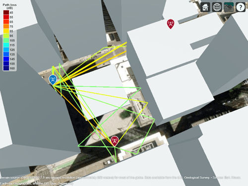
Perform ray tracing from the transmitter sites to the receiver site. Then, plot the propagation paths. By default, the raytrace function uses the shooting and bouncing rays (SBR) method and calculate paths with up to two reflections.
rays = raytrace([tx1 tx2],rx);
plot([rays{:}])
Ray tracing finds several ray paths to the receiver from each transmitter. From the map we can visually see the first transmitter is closer to the receiver than the second transmitter. We can also see the first transmitter has more reflected paths to the receiver. Display the propagation delays associated with each transmitter.
pd1 = [rays{1}.PropagationDelay]pd1 = 1×10
10-6 ×
0.3830 0.3839 0.5476 0.6482 0.5485 0.5486 0.6572 0.6945 0.7140 0.8874
pd2 = [rays{2}.PropagationDelay]pd2 = 1×5
10-6 ×
0.5967 0.5973 0.6059 0.6066 0.6255
Construct one channel filter for each transmitter site. Specify a sample rate of 30 MHz and use the minimum delay among the seven rays as the reference of time 0.
chanFilt1 = comm.ChannelFilter( ...
    "SampleRate",30e6, ...
    "PathDelays",pd1-min([pd1, pd2]))
chanFilt1 =
  comm.ChannelFilter with properties:

                 SampleRate: 30000000
                 PathDelays: [0 8.7598e-10 1.6459e-07 2.6516e-07 1.6553e-07 1.6565e-07 2.7417e-07 3.1151e-07 3.3105e-07 5.0442e-07]
          FilterDelaySource: 'Auto'
    NormalizeChannelOutputs: true
chanFilt2 = comm.ChannelFilter( ...
    "SampleRate",30e6, ...
    "PathDelays",pd2-min([pd1, pd2]))
chanFilt2 =
  comm.ChannelFilter with properties:

                 SampleRate: 30000000
                 PathDelays: [2.1372e-07 2.1434e-07 2.2294e-07 2.2357e-07 2.4247e-07]
          FilterDelaySource: 'Auto'
    NormalizeChannelOutputs: true
The individual channel filters for the two transmitters yield different filter delay values. Use the info object function of comm.ChannelFilter to show the filter delay of the two channel filters.
fd1 = chanFilt1.info.ChannelFilterDelay
fd1 = 7
fd2 = chanFilt2.info.ChannelFilterDelay
fd2 = 1
The two channel filters must have the same filter delay to combine the channel outputs at the receiver site. Customize the filter delay for each channel filter to use the larger value of the individually computed delay values.
set(chanFilt1,"FilterDelaySource","Custom", ...
    "FilterDelay",max(fd1,fd2));
set(chanFilt2,"FilterDelaySource","Custom", ...
    "FilterDelay",max(fd1,fd2));
Apply Receive Signal Combining
Set up system parameters, assigning only one isotropic antenna at each site.
Nt = 1;    % Number of transmit elements
Ns = 1000; % Samples per frame
M  = 64;   % Modulation order
Retrieve path gains from the computed rays. Assume the sites are static and no Doppler shift is introduced.
pg1  = 10.^(-[rays{1}.PathLoss]/20) .* ...
    exp(1i*[rays{1}.PhaseShift]);
pg2  = 10.^(-[rays{2}.PathLoss]/20) .* ...
    exp(1i*[rays{2}.PhaseShift]);
Generate a frame of random 64-QAM signals. Perform channel filtering for each transmitter site and receive signal combining. The combined 2x1 distributed MIMO channel has a filter delay of max(fd1,fd2).
x  = qammod(randi([0, M-1],Ns,Nt),M);
y = chanFilt1(x,pg1) + chanFilt2(x,pg2);
Appendix
[1] The osm file is downloaded from https://www.openstreetmap.org, which provides access to crowd-sourced map data all over the world. The data is licensed under the Open Data Commons Open Database License (ODbL), https://opendatacommons.org/licenses/odbl/.
Construct a channel filter object with the LTE Extended Vehicular A model (EVA) delay profile.
chanFilt = comm.ChannelFilter( ...
    'SampleRate', 30.72e6, ...
    'PathDelays', [0 30 150 310 370 710 1090 1730 2510]*1e-9);
Set up system parameters. There are two transmit and receive antennas.
[Nt, Nr] = deal(2);
Ns = 30720;
Np = length(chanFilt.PathDelays);
M  = 256;
Generate random 256-QAM signal and complex path gains.
x = qammod(randi([0, M-1], Ns, Nt), M);
g = complex(rand(Ns, Np, Nt, Nr), rand(Ns, Np, Nt, Nr));
Filter the signal with path gains for the EVA delay profile.
y = chanFilt(x, g);
Using one MIMO channel System object™ and two identically configured channel filter System objects, switch a link-level simulation between 3-by-2 downlink and reciprocal 2-by-3 uplink signal transmissions.
Define system parameters.
modOrder = 256;        % Modulation order
Nant1 = 3;             % Number of 'transmit' antennas
Nant2 = 2;             % Number of 'receive' antennas
Rs = 1e6;              % Sample rate
pd = [0 1.5 2.3]*1e-6; % Path delays
frmLen = 1e3;          % Frame length
Create a MIMO channel System object™, configuring it for path gain generation by disabling channel filtering.
chan = comm.MIMOChannel( ...
    'SampleRate',Rs, ...
    'PathDelays',pd, ...
    'AveragePathGains',[1.5 1.2 0.2], ...
    'MaximumDopplerShift',300, ...
    'SpatialCorrelationSpecification','none', ...
    'NumTransmitAntennas',Nant1, ...
    'NumReceiveAntennas',Nant2, ...
    'ChannelFiltering',false, ...
    'NumSamples',frmLen);
Create identical channel filter System objects for both transmission directions: one channel filter for the Nant1-by-Nant2 downlink channel (3 transmit antennas to 2 receive antennas) and a reciprocal channel filter for the Nant2-by-Nant1 uplink channel (2 transmit antennas to 3 receive antennas).
chanFiltDownlink = comm.ChannelFilter( ...
    'SampleRate',Rs, ...
    'PathDelays',pd);
chanFiltUplink = clone(chanFiltDownlink);
Downlink Transmission
Generate random path gains for one frame of the downlink 3-by-2 channel. Pass randomly generated 256-QAM signals through the 3-by-2 downlink channel.
pgDownlink = chan();
x = qammod(randi([0 modOrder-1],frmLen,Nant1),modOrder);
yDL = chanFiltDownlink(x,pgDownlink);
Uplink Transmission
Switch the link direction. Run the channel object to generate another frame of path gains, permuting its 3rd (Tx) and 4th (Rx) dimensions for the reciprocal uplink 2-by-3 channel. Pass randomly generated 256-QAM signals through the 2-by-3 reciprocal uplink channel.
pgUplink = permute(chan(),[1 2 4 3]);
x = qammod(randi([0 modOrder-1],frmLen,Nant2),modOrder);
yUL = chanFiltUplink(x,pgUplink);
Downlink and Uplink Array Dimensions
Show the sizes of the downlink and uplink path gain arrays returned by the MIMI channel object as an -by--by--by- array.
is the number of samples.
is the number of path delays.
is the number of transmit antennas.
Nant1for downlink andNant2for uplink.is the number of receive antennas.
Nant2for downlink andNant1for uplink.
size(pgDownlink)
ans = 1×4

        1000           3           3           2
size(pgUplink)
ans = 1×4

        1000           3           2           3
Show the size of the channel output matrices returned by the MIMI channel object as an -by- matrix. is the number of samples. is the number of receive antennas.
size(yDL)
ans = 1×2

        1000           2
size(yUL)
ans = 1×2

        1000           3
More About
The comm.ChannelFilter object supports an input signal
represented in an array, dlarray (Deep Learning Toolbox), or
gpuArray (Parallel Computing Toolbox).
If
Xis specified as adlarray,Yis returned as adlarrayobject.If
Xis adlarrayholding agpuArray, thenGmust be agpuArray.If
Xis adlarrayholding an array, thenGmust be an array.The number of batch observations (NB) is an optional dimension that can be added to the input for all supported data types. Variable NB is not supported. When the NB dimension is included:
For a list of Communications Toolbox™ features that support dlarray objects, see AI for Wireless.
Algorithms
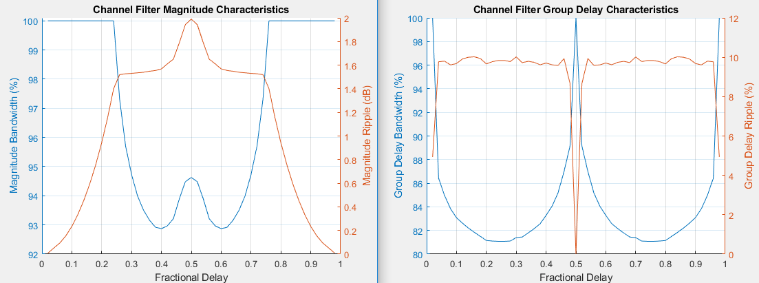
The channel filter implements a fractional delay (FD) finite impulse response (FIR) bandpass filter with a length of 16 coefficients for each candidate fractional delay at 0, 0.02, 0.04, …, 0.98.
Each discrete path is rounded to its nearest candidate fractional delay, so the delay error limit is 1% of the sample time. To achieve a group delay bandwidth exceeding 80% and a magnitude bandwidth exceeding 90%, the algorithm selects the optimal FIR coefficient values for each fractional delay, while satisfying the following criteria:
Group delay ripple ≤ 10%
Magnitude ripple ≤ 2 dB
Magnitude bandedge attenuation = 3 dB
The plots show bandwidths that satisfy the design criteria for group delay ripple, magnitude ripple, and magnitude bandedge attenuation.

For additional information, see the article A Matlab-based Object-Oriented Approach to Multipath Fading Channel Simulation at MATLAB® Central.
Extended Capabilities
Usage notes and limitations:
See System Objects in MATLAB Code Generation (MATLAB Coder).
This System object supports GPU array inputs. For more information, see Accelerate Simulation Using GPUs.
Usage notes and limitations:
Version History
Introduced in R2020bSee Also
Objects
MATLAB Command
You clicked a link that corresponds to this MATLAB command:
Run the command by entering it in the MATLAB Command Window. Web browsers do not support MATLAB commands.
选择网站
选择网站以获取翻译的可用内容,以及查看当地活动和优惠。根据您的位置,我们建议您选择:。
您也可以从以下列表中选择网站:
如何获得最佳网站性能
选择中国网站(中文或英文)以获得最佳网站性能。其他 MathWorks 国家/地区网站并未针对您所在位置的访问进行优化。
美洲
- América Latina (Español)
- Canada (English)
- United States (English)
欧洲
- Belgium (English)
- Denmark (English)
- Deutschland (Deutsch)
- España (Español)
- Finland (English)
- France (Français)
- Ireland (English)
- Italia (Italiano)
- Luxembourg (English)
- Netherlands (English)
- Norway (English)
- Österreich (Deutsch)
- Portugal (English)
- Sweden (English)
- Switzerland
- United Kingdom (English)