comm.CRCGenerator
Generate CRC code bits and append to input data
comm.CRCGenerator will be removed in a future release. Use crcGenerate
instead. (since R2024b) For information on updating your code, see Version History.
Description
The comm.CRCGenerator
System object™ generates cyclic redundancy check (CRC) code bits for each input frame and
appends them to the frame. For more information, see CRC Generator Operation.
To generate CRC code bits for each input frame and append them to the frame:
Create the
comm.CRCGeneratorobject and set its properties.Call the object with arguments, as if it were a function.
To learn more about how System objects work, see What Are System Objects?
Creation
Syntax
Description
crcgenerator = comm.CRCGenerator
crcgenerator = comm.CRCGenerator(Name,Value)comm.CRCGenerator('Polynomial','z^16 + z^14 + z + 1') configures the
CRC generator System object to append CRC-16 cyclic redundancy check bits to the input frame. Enclose
each property name in quotes.
crcgenerator = comm.CRCGenerator(poly,Name,Value)Polynomial property
set to poly, and the other specified properties set to the specified
values.
Properties
Usage
Description
Input Arguments
Output Arguments
Object Functions
To use an object function, specify the
System object as the first input argument. For
example, to release system resources of a System object named obj, use
this syntax:
release(obj)
Examples
Algorithms
The comm.CRCGenerator
System object supports generation and detection of CRC checksum by using the indirect or
direct CRC algorithm.
Indirect CRC Algorithm
The indirect CRC algorithm accepts a binary data vector, corresponding to a polynomial M, and appends a checksum of r bits, corresponding to a polynomial C. The concatenation of the input vector and the checksum then corresponds to the polynomial T = M×xr + C, since multiplying by xr corresponds to shifting the input vector r bits to the left. The algorithm chooses the checksum C so that T is divisible by a predefined polynomial P of degree r, called the generator polynomial.
The algorithm divides T by P, and sets the checksum equal to the binary vector corresponding to the remainder. That is, if T = Q×P + R, where R is a polynomial of degree less than r, the checksum is the binary vector corresponding to R. If necessary, the algorithm prepends zeros to the checksum so that it has length r.
The CRC generation feature, which implements the transmission phase of the CRC algorithm, does the following:
Left shifts the input data vector by r bits and divides the corresponding polynomial by P.
Sets the checksum equal to the binary vector of length r, corresponding to the remainder from step 1.
Appends the checksum to the input data vector. The result is the output vector.
The CRC detection feature computes the checksum for its entire input vector, as described above.
The CRC algorithm uses binary vectors to represent binary polynomials, in descending order of powers. For example, the vector [1 1 0 1] represents the polynomial x3 + x2 + 1.
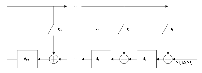
Bits enter the linear feedback shift register (LFSR) from the lowest index bit to the highest index bit. The sequence of input message bits represents the coefficients of a message polynomial in order of decreasing powers. The message vector is augmented with r zeros to flush out the LFSR, where r is the degree of the generator polynomial. If the output from the leftmost register stage d(1) is a 1, then the bits in the shift register are XORed with the coefficients of the generator polynomial. When the augmented message sequence is completely sent through the LFSR, the register contains the checksum [d(1) d(2) . . . d(r)]. This is an implementation of binary long division, in which the message sequence is the divisor (numerator) and the polynomial is the dividend (denominator). The CRC checksum is the remainder of the division operation.
Direct CRC Algorithm
This block diagram shows the direct CRC algorithm.
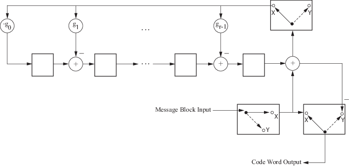
Where Message Block Input is and Code Word Output is
The initial step of the direct CRC encoding occurs with the three switches in position X. The algorithm feeds k message bits to the encoder. These bits are the first k bits of the code word output. Simultaneously, the algorithm sends k bits to the linear feedback shift register (LFSR). When the system completely feeds the kth message bit to the LFSR, the switches move to position Y. Here, the LFSR contains the mathematical remainder from the polynomial division. These bits are shifted out of the LFSR and they are the remaining bits (checksum) of the code word output.
The CRC generator appends CRC checksums to the input frame according to the specified generator polynomial and number of checksums per frame.
For a specific initial state of the internal shift register and k checksums per input frame:
The input signal is divided into k subframes of equal size.
Each of the k subframes are prefixed with the initial states vector.
The CRC algorithm is applied to each subframe.
The resulting checksums are appended to the end of each subframe.
The subframes are concatenated and output as a column vector.
For the scenario shown here, a 10-bit frame is input, a z3 + z2 + 1 generator polynomial computes the CRC checksum, the initial state is 0, and the number of checksums per frame is 2.

The input frame is divided into two subframes of size 5, and checksums of size 3 are computed
and appended to each subframe. The initial states are not shown because an initial state of
[0] does not affect the output of the CRC algorithm. The output
transmitted codeword frame has the size 5 + 3 + 5 + 3 = 16 bits.
References
[1] Sklar, Bernard. Digital Communications: Fundamentals and Applications. Englewood Cliffs, NJ: Prentice-Hall, 1988.
[2] Wicker, Stephen B. Error Control Systems for Digital Communication and Storage. Upper Saddle River, NJ: Prentice Hall, 1995.