General CRC Generator HDL Optimized
Generate CRC code bits and append them to input data
Libraries:
Communications Toolbox HDL Support /
Error Detection and Correction /
CRC
Description
The General CRC Generator HDL Optimized block, which is similar to the General CRC Generator block, generates a cyclic redundancy check (CRC) checksum and appends it to the input message. The General CRC Generator HDL Optimized block processing is optimized for HDL code generation. Instead of processing an entire frame at once, the block accepts and returns a data sample stream with accompanying control signals. The control signals indicate the validity of the samples and the boundaries of the frame. To achieve higher throughput, the block accepts vector data up to the CRC length and implements a parallel architecture.
Examples
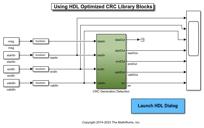
Using HDL Optimized CRC Library Blocks
Use the General CRC Generator HDL Optimized and General CRC Syndrome Detector HDL Optimized Simulink® blocks and then configure these blocks to meet the CRC-CCITT used in the IEEE® 802.11 standard [ 1 ].
Ports
Input
dataIn — Input data
scalar | vector
Input data, specified as one of these options.
Scalar – Specify an integer representing several bits. For this case, the block supports an unsigned integer (
uint8
,uint16
, oruint32
) orfixdt(0,N,0)
data type.Vector – Specify a vector of binary values. For this case, the block supports a
double
orBoolean
data type.
The data width must be less than or equal to the CRC length, and the CRC length must be divisible by the data width. For CRC-CCITT/CRC-16, the valid data widths are 16, 8, 4, 2, and 1.
Example: The uint8
vector input [0 0 0 1 0 0 1
1]
is equivalent to 19
.
Data Types: double
| uint8
| uint16
| uint32
| fixed point
| Boolean
startIn — Start of input frame indicator
Boolean scalar
Start of input frame indicator, specified as a Boolean scalar.
Data Types: Boolean
endIn — End of input frame indicator
Boolean scalar
End of input frame indicator, specified as a Boolean scalar.
Data Types: Boolean
validIn — Valid input data indicator
Boolean scalar
Valid input data indicator, specified as a Boolean scalar.
This is a control signal that indicates if the data on the dataIn port is valid.
Data Types: Boolean
Output
dataOut — Output data
scalar | vector
Output data with appended checksum, returned as a scalar or vector. The output data type and size are the same as the input data.
Data Types: double
| uint8
| uint16
| uint32
| Boolean
| fixed point
startOut — Start of output frame indicator
scalar
Start of output frame indicator, returned as a Boolean scalar.
Data Types: Boolean
endOut — End of output frame indicator
scalar
End of output frame indicator, returned as a Boolean scalar.
Data Types: Boolean
validOut — Valid output data indicator
scalar
Valid output data indicator, returned as a Boolean scalar.
This port is a control signal that indicates if the data on the dataOut port is valid.
Data Types: Boolean
Parameters
Polynomial — Generator polynomial
[1 0 0 0 1 0 0 0 0 0 0 1 0 0 0 0 1]
(default) | binary vector
Specify the generator polynomial as a binary vector with coefficients in descending order of powers. The vector length is equal to the degree of the polynomial plus 1.
Initial state — Initial conditions of shift register
0
(default) | binary scalar | binary vector
Specify initial conditions of the internal shift register as a binary, double-precision, or single-precision scalar or vector. For vector inputs, the length of the initial state must be equal to the degree of the generator polynomial.
Direct method — Method of calculating checksum
off
(default) | on
Specify the direct or indirect method for calculating the checksum.
Select this parameter for the block to use the direct algorithm for CRC checksum calculations.
Clear this parameter for the block to use the nondirect algorithm for CRC checksum calculations.
For more information about direct and nondirect algorithms, see Cyclic Redundancy Check Codes.
Reflect input — Input byte order
off
(default) | on
Specify the input byte order.
Select this parameter for the block to flip each input byte before it enters the shift register.
Clear this parameter for the block to pass the message data to the shift register unchanged.
The input data width must be a multiple of 8.
Reflect CRC checksum — Checksum byte order
off
(default) | on
Specify the checksum byte order.
Select this parameter for the block to flip each checksum byte before passing it to the final XOR stage.
Clear this parameter for the block to pass the checksum byte to the final XOR stage unchanged.
The input data width must be a multiple of 8.
Final XOR value — Checksum
0
(default) | binary scalar | binary vector
Specify the checksum as a binary, double-precision, or single-precision data type scalar or vector. The block performs XOR operation on the CRC checksum with this value before appending it to the input data.
If you specify a vector input, the vector length must be equal to the degree of the generator polynomial.
Algorithms
When you use a vector or integer input, the block implements a parallel CRC algorithm [1].
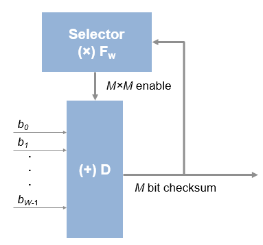
To provide high throughput for modern communications systems, the block implements the CRC algorithm with a parallel architecture. This architecture recursively calculates M bits of a CRC checksum for each W input bits. At the end of the frame, the final checksum result is appended to the message. For a polynomial length of M, the recursive checksum calculation for W bits in parallel is
FW is an M-by-M matrix that selects elements of the current state for the polynomial calculation with the new input bits. D is an M-element vector that provides the new input bits, ordered in relation to the generator polynomial and padded with zeros. The block implements the (×) with logical AND and (+) with logical XOR.
Timing Diagram
This waveform shows streaming data and the accompanying control signals for a CRC16 with an 8-bit binary vector input. To insert the checksum word, input frames must have enough space between them.
This waveform diagram shows continuous input data. The block also supports noncontinuous data. The output valid signal matches the input valid pattern.
Initial Delay
The General CRC Generator HDL Optimized block introduces a latency on the output. Assuming the input data is continuous, you can compute the latency by using the equation.
initialdelay = (CRC length/input data width) + 2.
Performance
The performance of the synthesized HDL code varies with your target and synthesis options. The generated HDL code is targeted to the AMD® Zynq® 7000 SoC ZC706 Evaluation Kit.
This table shows the resource and performance data synthesis results for a 16-by-1
Boolean
vector input, when you set the Polynomial
parameter to [ 1, 0, 0, 0, 1, 0, 0, 0, 0, 0, 0, 1, 0, 0, 0, 0, 1 ]
and
enable the Direct method parameter.
Slice LUTs | Slice Registers | Block RAM | Clock Frequency (MHz) |
---|---|---|---|
84 | 93 | 0 | 715.59 |
This table shows the resource and performance data synthesis results for a
ufix1
scalar input, when you set the Polynomial
parameter to [ 1, 0, 0, 0, 1, 0, 0, 0, 0, 0, 0, 1, 0, 0, 0, 0, 1 ]
and
enable the Direct method parameter.
Slice LUTs | Slice Registers | Block RAM | Clock Frequency (MHz) |
---|---|---|---|
74 | 93 | 0 | 726.51 |
References
[1] Campobello, G., G. Patane, and M. Russo. “Parallel Crc Realization.” IEEE Transactions on Computers 52, no. 10 (October 2003): 1312–19. https://doi.org/10.1109/TC.2003.1234528.
Extended Capabilities
C/C++ Code Generation
Generate C and C++ code using Simulink® Coder™.
Usage notes and limitations:
Not recommended for production code.
HDL Code Generation
Generate VHDL, Verilog and SystemVerilog code for FPGA and ASIC designs using HDL Coder™.
HDL Coder™ provides additional configuration options that affect HDL implementation and synthesized logic.
This block has one default HDL architecture.
ConstrainedOutputPipeline | Number of registers to place at
the outputs by moving existing delays within your design. Distributed
pipelining does not redistribute these registers. The default is
|
InputPipeline | Number of input pipeline stages
to insert in the generated code. Distributed pipelining and constrained
output pipelining can move these registers. The default is
|
OutputPipeline | Number of output pipeline stages
to insert in the generated code. Distributed pipelining and constrained
output pipelining can move these registers. The default is
|
Version History
Introduced in R2012a
MATLAB Command
You clicked a link that corresponds to this MATLAB command:
Run the command by entering it in the MATLAB Command Window. Web browsers do not support MATLAB commands.
Select a Web Site
Choose a web site to get translated content where available and see local events and offers. Based on your location, we recommend that you select: .
You can also select a web site from the following list
How to Get Best Site Performance
Select the China site (in Chinese or English) for best site performance. Other MathWorks country sites are not optimized for visits from your location.
Americas
- América Latina (Español)
- Canada (English)
- United States (English)
Europe
- Belgium (English)
- Denmark (English)
- Deutschland (Deutsch)
- España (Español)
- Finland (English)
- France (Français)
- Ireland (English)
- Italia (Italiano)
- Luxembourg (English)
- Netherlands (English)
- Norway (English)
- Österreich (Deutsch)
- Portugal (English)
- Sweden (English)
- Switzerland
- United Kingdom (English)
Asia Pacific
- Australia (English)
- India (English)
- New Zealand (English)
- 中国
- 日本Japanese (日本語)
- 한국Korean (한국어)