Concatenated OSTBC with TCM in Simulink
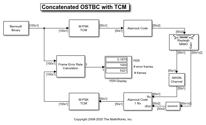
This model shows an orthogonal space-time block code (OSTBC) concatenated with trellis-coded modulation (TCM) for information transmission over a multiple-input multiple-output (MIMO) channel with 2 transmit antennas and 1 receive antenna.
Introduction
OSTBCs [ 1 ], [ 2 ] are an attractive technique for MIMO wireless communications. They exploit full spatial diversity order and enjoy symbol-wise maximum likelihood (ML) decoding. However, they offer no coding gain. The combiner for OSTBC at the receiver side provides soft information of the transmitted symbols, which can be utilized for decoding or demodulation of an outer code.
TCM [ 3 ] is a bandwidth efficient scheme that integrates coding and modulation to provide a large coding gain. Concatenating TCM with an inner code will usually offer an improved performance.
This example illustrates the advantages of an OSTBC and TCM concatenation scheme: the spatial diversity gain offered by OSTBC and the coding gain offered by TCM. For comparison, two reference models containing only TCM or OSTBC are also provided. The diversity and coding gains of the concatenation scheme over the reference models can be clearly observed from the simulation results. More discussions about concatenating OSTBC and TCM can be found in, for example, [ 4 ], [ 5 ] and references therein.
Structure of the Example

The individual tasks performed by the model include:
Random Data Generation
The Bernoulli Binary Generator block produces the information source for this simulation. The block generates a frame of 100 random bits. The Samples per frame parameter determines the length of the output frame (100 in this case).
Trellis-Coded Modulation (TCM)
The M-PSK TCM Encoder block modulates the message data from the Bernoulli Binary Generator to a PSK constellation that has unit average energy. The Trellis structure parameter accepts a MATLAB® structure to specify the trellis of the TCM. The M-ary number parameter specifies the size of the PSK constellation. In this example, we use the Ungerboeck TCM scheme for 8-PSK constellation with 8 trellis states [ 3 ]. Correspondingly, the Trellis structure parameter is set to poly2trellis([2 3], [1 2 0; 4 1 2]). This block has an output frame length of 50 as every two input bits produce one symbol.
The M-PSK TCM Decoder block uses the Viterbi algorithm for TCM to decode the signals from the OSTBC Combiner. The Operation mode parameter is set to Truncated to treat each frame independently. The Traceback depth parameter is set to 30 that, compared with the constraint length of the TCM, is long enough to ensure an almost lossless performance.
Orthogonal Space-Time Block Codes (OSTBC)
The OSTBC Encoder block encodes the information symbols from the TCM Encoder by using the Alamouti code [ 1 ] for 2 transmit antennas. The output of this block is a 50x2 matrix whose entries on each column correspond to the data transmitted over one antenna.
The OSTBC Combiner block combines the received signals from the receive antenna with the channel state information (CSI) to output the estimates of the transmitted symbols, which are then fed into the M-PSK TCM Decoder. In this example, the CSI is assumed perfectly known at the receiver side.
2x1 MIMO Channel
The MIMO Fading Channel block simulates a 2x1 frequency-flat Rayleigh fading channel. The Sample rate (Hz) parameter is set to 500000 that is calculated based on the input signal length and model sample time. The Maximum Doppler shift (Hz) parameter is set to 30. The reason for using this value is to make the MIMO channel behave like a quasi-static fading channel, i.e., it keeps constant during one frame transmission and varies along multiple frames.
Receiver Noise
The AWGN Channel block adds white Gaussian noises at the receiver side. The Mode parameter is set to Signal to noise ratio (SNR) mode and the Input signal power, referenced to 1 ohm (watts) parameter is set to 2 because the PSK constellation for TCM has unit average energy and the path gains of the MIMO channel are normalized.
Frame Error Rate (FER) Calculation
The Frame Error Rate (FER) Calculation subsystem compares the decoded bits with the original source bits per frame to detect errors and dynamically updates the FER along the simulation. The output of this subsystem is a three-element vector containing the FER, the number of error frames observed and the number of frames processed. This vector is from the Error Rate Calculation block and also saved as a MATLAB® workspace variable FER_Data to ease the simulation for multiple SNR values described below.
The Stop simulation parameter is checked to control the duration of the simulation. The simulation stops upon detecting a target number of error frames (specified by the Target number of errors parameter) or a maximum number of frames (specified by the Maximum number of symbols parameter), whichever comes first.

We now briefly describe the two reference models used for comparison.
TCM over Flat Rayleigh Fading Channel
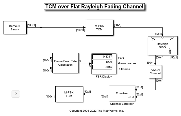
The model commtcm.slx simulates the TCM in the above concatenation scheme over a single-input single-output (SISO) flat Rayleigh fading channel. No space-time coding is used. The SISO Fading Channel block has the same specification as one subchannel of the 2x1 MIMO channel in the above model. The Input signal power, referenced to 1 ohm (watts) parameter of the AWGN Channel block is set to 1 as there is only one symbol transmitted per symbol period.

Channel Equalizer
The Channel Equalizer subsystem compensates the fading channel effect at the receiver side and its output is fed into the M-PSK TCM Decoder block for decoding. Note that the channel is flat Rayleigh fading in this model.

OSTBC over 2x1 Flat Rayleigh Fading Channel
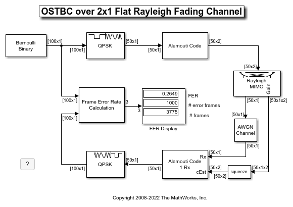
The model commostbc.slx replaces the TCM in the above concatenation scheme by a QPSK modulation so that both the models have the same symbol (frame) rate. It uses the same 2x1 MIMO Fading Channel block as in the TCM-OSTBC concatenation model. The QPSK Modulator Baseband block maps the information bits to a QPSK constellation and the QPSK Demodulator Baseband block demodulates the signals from the OSTBC Combiner.

Performance Results
Creating a FER vs. SNR performance curve requires simulations for multiple SNR values, which can be performed by using the sim command. We start by defining some simulation parameters
      SNRRange = 10:2:24;
      maxNumErrs = 1e3;  % Number of frame errors
      maxNumFrms = 5e6;  % Number of frames processed
and then initialize a figure in order to visualize the performance results.
      fig = figure;
      grid on;
      hold on;
      ax = fig.CurrentAxes;
      ax.YScale = 'log';
      xlim([SNRRange(1), SNRRange(end)]);
      ylim([1e-4 1]);
xlabel('SNR (dB)');
ylabel('FER');
fig.NumberTitle = 'off';
fig.Rrenderer = 'zbuffer';
fig.Name = 'Concatenated OSTBC with TCM';
title('Concatenated OSTBC with TCM');To simulate the OSTBC-TCM concatenated model, we execute the following commands that run the simulation multiple times and plot the results.
      FERTCMOSTBC = zeros(length(SNRRange), 3);
      for idx = 1:length(SNRRange)
          SNR = SNRRange(idx);
          sim('commtcmostbc');
          FERTCMOSTBC(idx, :) = FER_Data;
          h1 = semilogy(SNRRange(1:idx), FERTCMOSTBC(1:idx, 1), 'r+');
      end
      fitFERTCMOSTBC = berfit(SNRRange, FERTCMOSTBC(:, 1)');
      semilogy(SNRRange, fitFERTCMOSTBC, 'r');
Similarly, we can simulate the two reference models via executing
      FERTCM = zeros(length(SNRRange), 3);
      for idx = 1:length(SNRRange)
          SNR = SNRRange(idx);
          sim('commtcm');
          FERTCM(idx, :) = FER_Data;
          h2 = semilogy(SNRRange(1:idx), FERTCM(1:idx, 1), 'gp');
      end
      fitFERTCM = berfit(SNRRange, FERTCM(:, 1)');
      semilogy(SNRRange, fitFERTCM, 'g');
FEROSTBC = zeros(length(SNRRange), 3);
for idx = 1:length(SNRRange)
SNR = SNRRange(idx);
sim('commostbc');
FEROSTBC(idx, :) = FER_Data;
h3 = semilogy(SNRRange(1:idx), FEROSTBC(1:idx, 1), 'bo');
end
fitFEROSTBC = berfit(SNRRange, FEROSTBC(:, 1)');
semilogy(SNRRange, fitFEROSTBC, 'b');legend([h1, h2, h3], 'TCM + OSTBC', 'TCM', 'OSTBC');
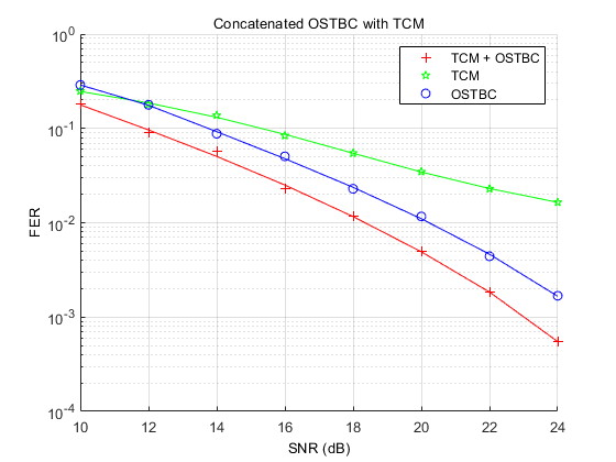
The FER vs. SNR performance result is presented in the following figure.

As expected, the concatenation scheme provides a significant diversity gain over the TCM scheme and about 2dB coding gain over the Alamouti code.
Further Exploration
Upon loading the simulation models, variables are created in the MATLAB® workspace which can be modified to explore the effects of different parameter settings such as Samples per frame (variable frameLen), Trellis structure (variable trellis) or Maximum Doppler shift (Hz) (variable maxDopp) on the system performance.
Selected Bibliography
S. M. Alamouti, "A simple transmit diversity technique for wireless communications," IEEE® Journal on Selected Areas in Communications, vol. 16, no. 8, pp. 1451-1458, Oct. 1998.
V. Tarokh, H. Jafarkhami, and A. R. Calderbank, "Space-time block codes from orthogonal designs," IEEE Transactions on Information Theory, vol. 45, no. 5, pp. 1456-1467, Jul. 1999.
G. Ungerboeck, "Channel coding with multilevel/phase signals," IEEE Transactions on Information Theory, vol. IT-28, no. 1, pp. 55-67, Jan. 1982.
S. M. Alamouti, V. Tarokh, and P. Poon, "Trellis-coded modulation and transmit diversity: Design criteria and performance evaluation," in Proc. IEEE International Conference on Universal Personal Communications (ICUPC'98), Florence, Italy, Oct. 1998, pp. 703-707.
Y. Gong and K. B. Letaief, "Concatenated space-time block coding with trellis coded modulation in fading channels," IEEE Transactions on Wireless Communications, vol. 1, no. 4, pp. 580-590, Oct. 2002.