Design LQG Tracker Using Control System Designer
This example shows how to use LQG synthesis to design a feedback controller for a disk drive read/write head using Control System Designer.
For details about the system and model, see Chapter 14 of "Digital Control of Dynamic Systems," by Franklin, Powell, and Workman.
Disk Drive Model
Below is a picture of the system to be modeled.
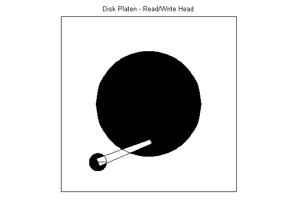
The model input is the current driving the voice coil motor, and the output is the position error signal (PES, in % of track width). To learn more about the 10th order model, see Digital Servo Control of a Hard-Disk Drive. The plant includes a small time delay. For the purpose of this example, ignore this delay.
load diskdemo
Gr = tf(1e6,[1 12.5 0]);
Gf1 = tf(w1*[a1 b1*w1],[1 2*z1*w1 w1^2]); % first  resonance
Gf2 = tf(w2*[a2 b2*w2],[1 2*z2*w2 w2^2]); % second resonance
Gf3 = tf(w3*[a3 b3*w3],[1 2*z3*w3 w3^2]); % third  resonance
Gf4 = tf(w4*[a4 b4*w4],[1 2*z4*w4 w4^2]); % fourth resonance
G = (ss(Gf1)+Gf2+Gf3+Gf4) * Gr;     % convert to state space for accuracy
Design Overview
In this example, design a full-ordered LQG tracker, which places the read/write head at the correct position. Tune the LQG tracker to achieve specific performance requirements and reduce the controller order as much as possible. For example, turn the LQG tracker into a PI controller format.
Open Control System Designer
Open Control System Designer, importing the plant model.
controlSystemDesigner(G)
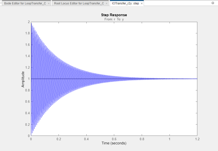
By default, Control System Designer displays the step response of the closed-loop system along with Bode and root locus graphical editors for the open-loop response.
To view only the step response, click the arrow in the top right corner of the plot and select Tile All > Single.
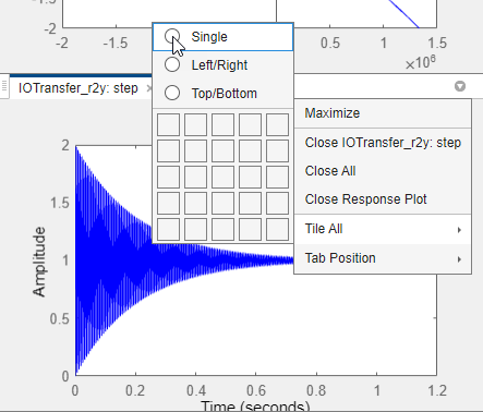
The app expands the step response plot in the document area.Details about how to use Control System Designer are described in Getting Started with the Control System Designer.

The default unity gain compensator produces a stable closed-loop system with large oscillations.
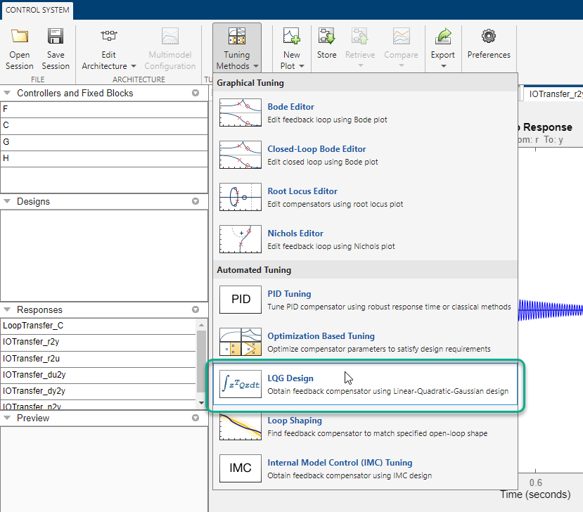
Design a Full-Order LQG Tracker
To design an LQG tracker, click Tuning Methods, and select LQG Design.
In the LQG Design dialog box, in the Specifications section, set requirements on the controller performance:
Controller response - Specify the controller transient behavior. You can make the controller more aggressive at disturbance rejection or more robust against plant uncertainty. If you believe your model is accurate and that the manipulated variable has a large enough range, an aggressive controller is preferable.
Measurement noise - Specify an estimate of the level of output measurement noise for your application. To produce a more robust controller, specify a larger noise estimate.
Desired controller order - Specify your controller order preference.
For an initial full-order controller design, set the Controller response and Measurement sliders to the center and select a Desired Controller Order of 11.

Click Update Compensator. The new Compensator is displayed, and the step response updates.

To design a more aggressive controller, move the Controller response slider to the far left and click Update Compensator. The more aggressive controller reduces the overshoot by 50% and reduces the settling time by 70%.
Design a Reduced-Order LQG Tracker
To create a PI controller, reset the Controller response slider to the middle value, and set the Desired Controller Order to 1.

Click Update Compensator.
This controller produces a heavily oscillating closed-loop system. To make the controller less aggressive, move the Controller response slider to the right.

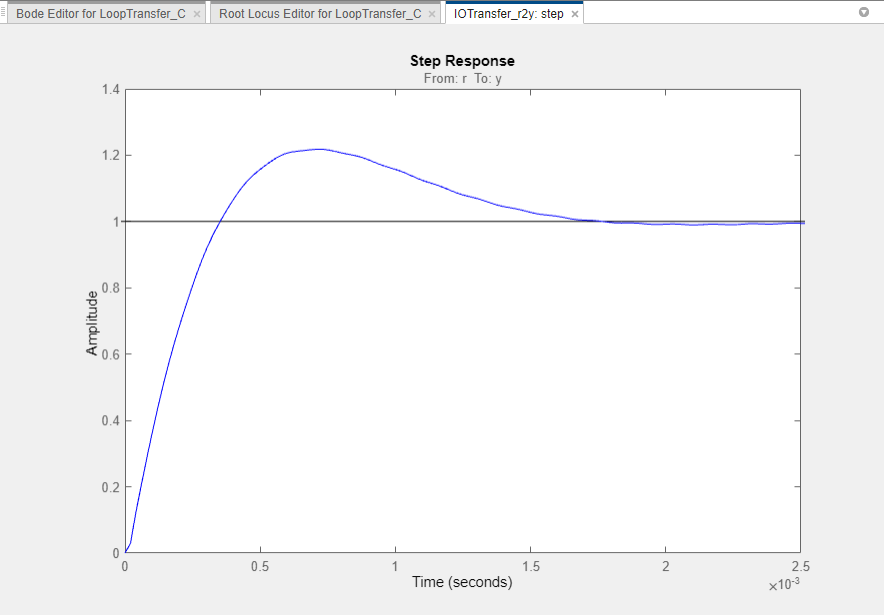
Click Update Compensator.
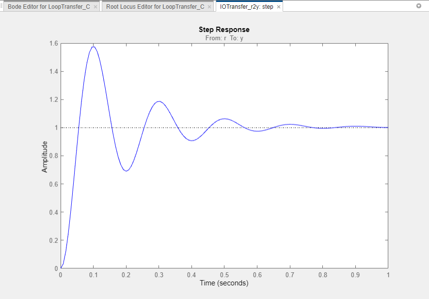
The step response shows that the PI controller design provides a good starting point for optimization-based design. For more information, see Getting Started with the Control System Designer.