Design Compensator Using Automated Tuning Methods
This example shows how to tune a compensator using automated tuning methods in Control System Designer.
Select Tuning Method
To select an automated tuning method, in Control System Designer, click Tuning Methods.
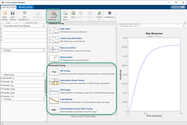
Select one of the following tuning methods:
PID Tuning— Tune PID gains to balance performance and robustness or use classical tuning formulas.Optimization Based Tuning— Optimize compensator parameters using design requirements implemented in graphical tuning and analysis plots (requires Simulink® Design Optimization™ software).LQG Design— Design a full-order stabilizing feedback controller as a linear-quadratic-Gaussian (LQG) tracker.Loop ShapingFree-form structure— Find a full-order stabilizing feedback controller with a specified open-loop bandwidth or shape (requires Robust Control Toolbox™ software).Fixed structure— Tune a user-specified stabilizing feedback controller with a specified open-loop bandwidth or shape.
Internal Model Control (IMC) Tuning— Obtain a full-order stabilizing feedback controller using the IMC design method.
Select Compensator and Loop to Tune
In the dialog box for your selected tuning method, in the Compensator section, select the compensator and loop to tune. You can use the Compensator Editor to specify your compensator structure. For more information, see Edit Compensator Dynamics in Control System Designer.
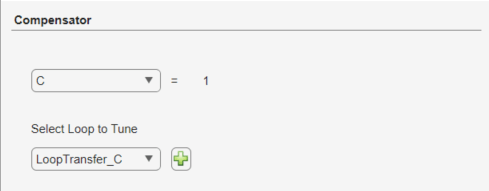
Compensator — Select a compensator to tune from the drop-down list. The app displays the current compensator transfer function.
Select Loop to Tune — Select an existing open-loop transfer function to tune from the drop-down list. You can select any open-loop transfer function from the Data Browser that includes the selected compensator in series.
Add New Loop — Create a new loop to tune. In the Open-Loop Transfer Function dialog box, select signals and loop openings to configure the loop transfer function.
Note
For optimization-based tuning, you do not specify the compensator and loop to tune in this way. Instead, you define the compensator structure and select compensator and prefilter parameters to optimize. For more information, see Select Tunable Compensator Elements (Simulink Design Optimization).
The structure of the compensator is maintained as poles and zeros after tuning except when performing optimization-based tuning.
PID Tuning
Using Control System Designer, you can automatically tune any of the following PID controller types:
P — Proportional-only control
I — Integral-only control
PI — Proportional-integral control
PD — Proportional-derivative control
PDF — Proportional-derivative control with a low-pass filter on the derivative term
PID — Proportional-integral-derivative control
PIDF — Proportional-integral-derivative control with a low-pass filter on the derivative term
To open the PID Tuning dialog box, in Control System Designer, click Tuning Methods, and select PID Tuning.

Robust Response Time
The robust response time algorithm automatically tunes PID parameters to balance performance and robustness. Using the robust response time method, you can:
Tune all parameters for any type of PID controller.
Design for plants that are stable, unstable, or integrating.
To tune your compensator using this method:
In the PID Tuning dialog box, in the Specifications section, in the Tuning method drop-down list, select
Robust
                                response time
.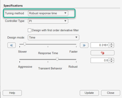
Select a Controller type. If you choose PD or PID, check Design with first order derivative filter to design a PDF or PIDF controller, respectively.
Tip
Adding derivative action to the controller gives the algorithm more freedom to achieve both adequate phase margin and faster response time.
In the Design mode drop-down list, select one of the following:
Time— Specify controller performance using time-domain parameters.
Response Time — Specify a faster or slower controller response time. To modify the response time by a factor of ten, use the left or right arrows.
Transient Behavior — Specify the controller transient behavior. You can make the controller more aggressive at disturbance rejection or more robust against plant uncertainty.
Frequency— Specify controller performance using frequency-domain parameters.
Bandwidth — Specify the closed-loop bandwidth of the control system. To produce a faster response time, increase the bandwidth. To modify the bandwidth by a factor of ten, use the left or right arrows.
Phase Margin — Specify a target phase margin for the system. To reduce overshoot and create a more robust controller, increase the phase margin.
To apply the specified controller design to the selected compensator, click Update Compensator.
Note
If you previously specified the controller structure manually or using a different automated tuning method, that structure is lost when you click Update Compensator.
By default, the app automatically computes controller parameters for balanced performance and robustness. To revert to these default parameters at any time, click Reset Parameters.
Classical Design Formulas
You can use classical PID design formulas to tune P, PI, PID, and PIDF controllers. These design formulas:
Require a stable or integrating plant. For more information about the effective plant seen by the compensator, see Effective Plant for Tuning.
Cannot tune the derivative filter. If you select a PIDF controller, the classical design methods set the filter time constant to Td/10, where Td is the tuned derivative time.
To tune your compensator using a classical method:
In the PID Tuning dialog box, in the Specifications section, in the Tuning method drop-down list, select
Classical
                                design formulas
.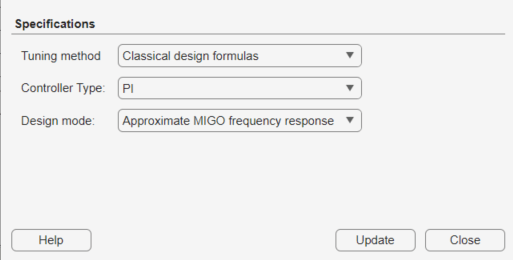
Select a Controller type.
Tip
Adding derivative action to the compensator gives the algorithm more freedom to achieve both adequate phase margin and faster response time.
In the Design mode drop-down list, select a classical design formula.

Approximate MIGO frequency response— Compute controller parameters using closed-loop, frequency-domain, approximate M-constrained integral gain optimization (see [1]).Approximate MIGO step response— Compute controller parameters using open-loop, time-domain, approximate M-constrained integral gain optimization (see [1]).Chien-Hrones-Reswick— Approximate the plant as a first-order model with a time delay, and compute PID parameters using a Chien-Hrones-Reswick lookup table for 0% overshoot and disturbance rejection (see [2]).Skogestad IMC— Approximate the plant as a first-order model with a time delay, and compute PID parameters using Skogestad design rules (see [3]).Note
This method is different from selecting Internal Model Control Tuning as the full-order compensator tuning method.
Ziegler-Nichols frequency response— Compute controller parameters from a Ziegler-Nichols lookup table, based on the ultimate gain and frequency of the system (see [2]).Ziegler-Nichols step response— Approximate the plant as a first-order model with a time delay, and compute PID parameters using the Ziegler-Nichols design method (see [2]).
Apply the specified controller design to the selected compensator. Click Update Compensator.
Note
If you previously specified the controller structure manually or using a different automated tuning method, that structure is lost when you click Update Compensator.
Optimization-Based Tuning
Optimization-based tuning is available only if you have Simulink Design Optimization software installed. You can use this method to design control systems for LTI models by optimizing controller parameters.
Note
Optimization-based tuning only changes the values of controller parameters and not the controller structure itself. For information on adding or removing compensator elements, see Edit Compensator Dynamics in Control System Designer.
To design a controller using optimization-based tuning:
Define the structure of the compensators you want to tune. Typically, you design an initial controller either manually or using a different automated tuning method.
Open the Response Optimization dialog box. In Control System Designer, click Tuning Methods, and select Optimization-Based Tuning.
Select compensator parameters to optimize. On the Compensators tab, in the Optimize column, select the compensator elements to tune.
You can optimize elements for any compensator listed in the Data Browser.
Any elements that you do not select in the Optimize column remain at their current values during optimization.
For each compensator element, specify:
Initial guess — Starting point for the optimization algorithm. To use the current element Value as the Initial guess, click a row in the table, and click Use Value as Initial guess.
Minimum and Maximum bounds on the element value. The optimization constrains the search results to the specified range.
Typical value scaling factor for normalizing the compensator elements.
On the Design Requirements tab, in the Optimize column, select the design requirements to satisfy during optimization.
Each design requirement is associated with a plot of a specific response in the Data Browser.
For information on adding and editing design requirements, see Design Requirements.
(optional) Configure optimization options. On the Optimization tab, click Optimization options.
Click Start Optimization.
For examples of optimization-based tuning, see Optimize LTI System to Meet Frequency-Domain Requirements (Simulink Design Optimization) and Design Optimization-Based PID Controller for Linearized Simulink Model (GUI) (Simulink Design Optimization).
LQG Design
Linear-quadratic-Gaussian (LQG) control is a technique for designing optimal dynamic regulators and setpoint trackers. This technique allows you to trade off performance and control effort, and to take into account process disturbances and measurement noise.
LQG synthesis generates a full-order feedback controller that guarantees closed-loop stability. The designed controller contains an integrator, which guarantees zero steady-state error for plants without a free differentiator.
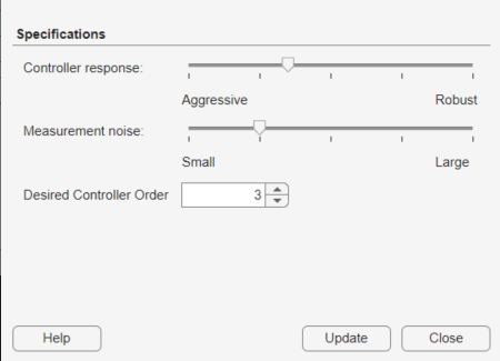
To design an LQG controller:
Open the LQG Synthesis dialog box. In Control System Designer, click Tuning Methods, and select LQG Synthesis.
Specify the transient behavior of the controller using the Controller response slider. You can make the controller more aggressive at disturbance rejection or more robust against plant uncertainty. If you believe your model is accurate and that the manipulated variable has a large enough range, an aggressive controller is preferable.
Specify an estimate of the level of output measurement noise for your application using the Measurement noise slider. To produce a more robust controller, specify a larger noise estimate.
Specify your controller order preference using the Desired controller order slider. The maximum controller order is dependent on the effective plant dynamics.
Apply the specified controller design to the selected compensator. Click Update Compensator.
Note
If you previously specified the controller structure manually or using a different automated tuning method, that structure is lost when you click Update Compensator.
For an example of LQG synthesis using Control System Designer, see Design LQG Tracker Using Control System Designer.
Loop Shaping
You can use loop shaping to design SISO compensators in Control System Designer for free-form or fixed structure compensators. Loop shaping to design free-form compensators requires a Robust Control Toolbox license. Loop shaping generates a stabilizing feedback controller to match, as closely as possible, a target loop shape. You can specify this loop shape as a bandwidth or an open-loop frequency response.
To design a controller using loop shaping:
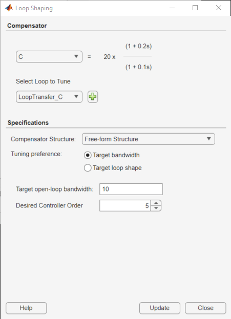
Open the Loop Shaping dialog box. In Control System Designer, click Tuning Methods, and select Loop Shaping.
Select one of the following tuning preferences:
Compensator Structure — Choose one of the following compensator structures:
Free-form structure— If you have Robust Control Toolbox software installed, you can use a free-form compensator structure. Use the Desired controller order slider to specify your controller order preference. You can use the Compensator Editor to specify your compensator structure. For more information about the Compensator Editor, see Edit Compensator Dynamics in Control System Designer.Fixed structure— When you selectFixed Structure, Control System Designer will use the supplied controller order to perform the automated loop shaping.
Target bandwidth — Specify a Target open-loop bandwidth, , to produce a loop shape of the specified bandwidth over an integrator, .
Target loop shape — Specify the Target open-loop shape as a
tf,ss, orzpkobject. To limit the frequencies over which to match the target loop shape, specify the Frequency range for loop shaping as a two-element row vector.
Specify your controller order preference using the Desired controller order slider when using a free-form compensator structure. The maximum controller order is dependent on the effective plant dynamics. When you use a fixed compensator structure, Control System Designer will use the supplied controller order to perform the automated loop shaping.
Apply the specified controller design to the selected compensator. Click Update Compensator.
Note
If you previously specified the controller structure manually or using a different automated tuning method, that structure is lost when you click Update Compensator.
Internal Model Control Tuning
Internal model control (IMC) uses a predictive model of the plant dynamics to compute control actions. IMC design generates a full-order feedback controller that guarantees closed-loop stability when there is no model error. The tuned compensator also contains an integrator, which guarantees zero steady-state offset for plants without a free differentiator. You can use this tuning method for both stable and unstable plants.
To design an IMC controller:
Select and configure the IMC control architecture. In Control System Designer, click Edit Architecture.
In the Edit Architecture dialog box, select the fifth control architecture, and import the plant model, G1, predictive model, G2, and disturbance model Gd.

Click OK.
Open the Internal Model Control (IMC) Tuning dialog box. In Control System Designer, click Tuning Methods, and select Internal Model Control (IMC) Tuning.
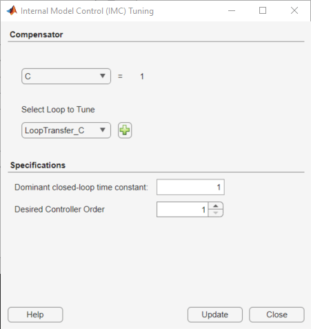
Specify a Dominant closed-loop time constant. The default value is 5% of the open-loop settling time. In general, increasing this value slows down the closed-loop system and makes it more robust.
Specify your controller order preference using the Desired controller order slider. The maximum controller order is dependent on the effective plant dynamics.
Apply the specified controller design to the selected compensator. Click Update Compensator.
Note
If you previously specified the controller structure manually or using a different automated tuning method, that structure is lost when you click Update Compensator.
For an example of IMC tuning, see Design Internal Model Controller for Chemical Reactor Plant.
References
[1] Åström, K. J. and Hägglund, T. "Replacing the Ziegler-Nichols Tuning Rules." Chapter 7 in Advanced PID Control, Research Triangle Park, NC: Instrumentation, Systems, and Automation Society, 2006, pp. 233–270.
[2] Åström, K. J. and Hägglund, T. "Ziegler-Nichols' and Related Methods." Section 6.2 in Advanced PID Control, Research Triangle Park, NC: Instrumentation, Systems, and Automation Society, 2006, pp. 167–176.
[3] Skogestad, S., "Simple analytic rules for model reduction and PID controller tuning." Journal of Process Control, Vol. 13, No. 4, 2003, pp. 291–309.