zpk
零极点增益模型
说明
使用 zpk 创建零极点增益模型,或将动态系统模型转换为零极点增益形式。
零极点增益模型是传递函数的分解形式表示。例如,假设有以下连续时间 SISO 传递函数:
G(s) 可以分解为零极点增益形式,如下所示:
SISO 零极点增益模型的更一般表示如下:
此处,z 和 p 是实数值或复数值零极点的向量,k 是实数值或复数值标量增益。对于 MIMO 模型,每个 I/O 通道由一个这样的传递函数表示:hij(s)。
您可以通过直接指定其极点、零点或增益或通过将另一种类型的模型(如状态空间模型 ss)转换为零极点增益形式来创建零极点增益模型对象。
您还可以使用 zpk 来创建广义状态空间 (genss) 模型或不确定状态空间 (uss (Robust Control Toolbox)) 模型。
创建对象
语法
描述
创建 ZPK 模型
转换为 ZPK 模型
sys = zpk(ltiSys,Name=Value)ltiSys 的截断 zpk 表示。由于这种方法会为每个输入-输出对组计算零点,因此最适合输入-输出规模较小的模型。 (自 R2025a 起)
输入参量
零极点增益模型的零点,指定为:
行向量,用于 SISO 模型。例如,使用
[1,2+i,2-i]创建一个在s = 1、s = 2+i和s = 2-i处有零点的模型。有关示例,请参阅连续时间 SISO 零极点增益模型。由行向量组成的
Ny×Nu元胞数组,用于指定 MIMO 零极点增益模型,其中Ny是输出数目,Nu是输入数目。有关示例,请参阅离散时间 MIMO 零极点增益模型。
例如,如果 a 是标称值为 3 的 realp 可调参数,则您可以使用 zeros = [1 2 a] 创建一个 genss 模型,其中在 s = 1 和 s = 2 处具有零点,在 s = 3 处具有可调零点。
当您使用此输入参量创建一个 zpk 模型时,此参量用于设置属性 Z 的初始值。
零极点增益模型的极点,指定为:
行向量,用于 SISO 模型。有关示例,请参阅连续时间 SISO 零极点增益模型。
由行向量组成的
Ny×Nu元胞数组,用于指定 MIMO 零极点增益模型,其中Ny是输出数目,Nu是输入数目。有关示例,请参阅离散时间 MIMO 零极点增益模型。
它也是 zpk 对象的一个属性。此输入参量设置属性 P 的初始值。
零极点增益模型的增益,指定为:
标量,用于 SISO 模型。有关示例,请参阅连续时间 SISO 零极点增益模型。
Ny×Nu矩阵,用于指定 MIMO 零极点增益模型,其中Ny是输出数目,Nu是输入数目。有关示例,请参阅离散时间 MIMO 零极点增益模型。
它也是 zpk 对象的一个属性。此输入参量设置属性 K 的初始值。
采样时间,指定为标量。它也是 zpk 对象的一个属性。此输入参量设置属性 Ts 的初始值。
动态系统,指定为 SISO 或 MIMO 动态系统模型或动态系统模型数组。您可以使用的动态系统包括:
连续时间或离散时间数值 LTI 模型,如
tf、zpk、ss或pid模型。如果
ltiSys是稀疏状态空间模型(sparss或mechss),软件会在指定的关注频带内计算截断零极点增益逼近。对于稀疏模型,请使用名称-值参量来指定计算选项。如果您不指定任何选项,软件最多可计算幅值最小的前 1000 个零极点。此外,获得截断零极点增益逼近仅适用于具有有效sparss表示的模型。 (自 R2025a 起)广义或不确定的 LTI 模型,如
genss或uss(Robust Control Toolbox) 模型。(使用不确定模型需要 Robust Control Toolbox™ 许可证。)生成的零极点增益模型假设
对于可调控制设计模块,采用可调组件的当前值。
对于不确定的控制设计模块,采用标称模型值。
辨识的 LTI 模型,如
idtf(System Identification Toolbox)、idss(System Identification Toolbox)、idproc(System Identification Toolbox)、idpoly(System Identification Toolbox) 和idgrey(System Identification Toolbox) 模型。要选择要转换的辨识模型的组件,请指定component。如果未指定component,则默认情况下,tf会转换所辨识模型的被测组件。(使用辨识模型需要 System Identification Toolbox™ 软件。)无法将辨识的非线性模型转换为
zpk模型对象。您可以首先使用线性逼近函数,如linearize和linapp(此功能需要 System Identification Toolbox 软件。)
静态增益,指定为标量或矩阵。系统的静态增益或稳态增益表示在稳态条件下输出与输入的比率。
要转换的辨识模型的组件,指定为以下项之一:
'measured'- 转换sys的被测组件。'noise'- 转换sys的噪声分量'augmented'- 转换sys的被测组件和噪声分量。
component 仅在 sys 是辨识的 LTI 模型时适用。
有关辨识的 LTI 模型及其被测组件和噪声分量的详细信息,请参阅Identified LTI Models。
名称-值参数
以 Name1=Value1,...,NameN=ValueN 的形式指定可选参量对组,其中 Name 是参量名称,Value 是对应的值。名称-值参量必须出现在其他参量之后,但对各个参量对组的顺序没有要求。
示例: sys = zpk(sparseSys,Focus=[0 100],Display="off")
自 R2025a 起
在零极点计算期间使用并行计算,指定为数值或逻辑 0 (false) 或 1 (true)。
当 UseParallel 设置为 true 时,您可以明确选择扩展到您的首选并行环境。启用并行计算可以提高零极点计算的性能。但是,即使 UseParallel 设置为 false,算法也可以使用内置的多线程来充分利用本地资源。有关详细信息,请参阅 MATLAB Multicore。
此选项需要 Parallel Computing Toolbox™ 许可证。
自 R2025a 起
滚降斜率,指定为非正标量或矩阵。
对于 SISO 模型或者所有输入-输出对组的斜率相同的 MIMO 模型,使用标量值。
对于每个输入-输出对组的斜率不同的 MIMO 模型,使用矩阵。
通过此选项,您可以指定在超出指定频率范围后,逼近应如何滚降。例如,Slope 为 -2 可确保增益在超过 fmax 后,以至少 -40 dB/十倍频程的速率(滚降率为 1/s2)滚降。
自 R2025a 起
感兴趣的频率范围,指定为 [0,fmax] 形式的向量。当您指定关注的频率范围时,软件仅会计算固有频率在此范围内的极点。对于离散时间模型,软件通过突斯汀变换来逼近等效的固有频率。
由于 zpk 会计算指定频率范围内的所有零极点,因此您通常会指定一个低频范围来限制计算大量零极点。默认情况下,不指定关注的频率范围 ([0 Inf]),并且算法最多计算 MaxNumber 个零极点。
自 R2025a 起
要计算的零极点的最大数目,指定为正整数。此值限制算法计算的零极点的数目,以及原始稀疏模型的逼近阶数。
自 R2025a 起
频谱偏移,指定为有限标量。
通过对 A-sigma*E 使用逆幂迭代法,软件会计算固有频率在指定范围 [0,fmax] 内的极点,从而获得最接近偏移量 sigma 的特征值。当 A 为奇异矩阵且 sigma 为零时,由于不存在逆矩阵,算法会失败。因此,对于具有积分作用的稀疏模型(s = 0,或对于离散时间模型,在 z = 1 时),您可以使用此选项将极点或零点隐式地偏移至最接近此偏移值的值。请指定一个不等于原始模型现有极点或零点值的偏移值。
自 R2025a 起
计算的零极点的精度容差,指定为正有限标量。此值控制逆幂迭代中计算得到的特征值的收敛。
自 R2025a 起
显示或隐藏进度报告,指定为 "off" 或 "on"。
属性
系统零点,指定为:
由传递函数零点或分子根组成的元胞数组,用于 SISO 模型。
由一个 MIMO 模型中每个 I/O 对组的零点的行向量组成的
Ny×Nu元胞数组,其中Ny是输出数目,Nu是输入数目。
Z 的值可以是实数值,也可以是复数值。
系统极点,指定为:
由传递函数极点或分母根组成的元胞数组,用于 SISO 模型。
由 MIMO 模型中每个 I/O 对组的极点的行向量组成的
Ny×Nu元胞数组,其中Ny是输出数目,Nu是输入数目。
P 的值可以是实数值,也可以是复数值。
系统增益,指定为:
标量,用于 SISO 模型。
一个
Ny×Nu矩阵,用于存储 MIMO 模型的每个 I/O 对组的增益值,其中Ny是输出数目,Nu是输入数目。
K 的值可以是实数值,也可以是复数值。
指定如何分解分子多项式和分母多项式以进行显示,指定为以下值之一:
'roots'- 使用多项式根的位置来显示因子。'roots'是DisplayFormat的默认值'frequency'- 使用根固有频率 ω0 和阻尼比 ζ 来显示因子。'frequency'显示格式不适用于具有Variable值'z^-1'或'q^-1'的离散时间模型。'time constant'- 使用根时间常数 τ 和阻尼比 ζ 来显示因子。'time constant'显示格式不适用于具有Variable值'z^-1'或'q^-1'的离散时间模型。
对于连续时间模型,下表显示多项式因子在每种显示格式中的排列方式。
DisplayName 值 | 一阶因子(实根 ) | 二阶因子(复根对 ) |
|---|---|---|
'roots' | 其中 | |
'frequency' | 其中 | 其中 |
'time constant' | 其中 | 其中 |
对于离散时间模型,多项式因子的排列类似于连续时间模型,但进行了以下变量代换:
其中 Ts 是采样时间。在离散时间中,τ 和 ω0 紧密匹配等效连续时间根的时间常数和固有频率,前提是满足以下条件:。
零极点增益模型显示变量,指定为以下项之一:
's'- 连续时间模型的默认值'z'- 离散时间模型的默认值'p'- 等效于's''q'- 等效于'z''z^-1'-'z'的倒数'q^-1'- 等效于'z^-1'
传输延迟,指定为以下项之一:
标量 - 为 SISO 系统指定传输延迟,或为 MIMO 系统的所有输入/输出对组指定相同的传输延迟。
Ny×Nu数组 - 为 MIMO 系统的每个输入/输出对组指定单独的传输延迟。此处,Ny是输出数目,Nu是输入数目。
对于连续时间系统,以 TimeUnit 属性指定的时间单位指定传输延迟。对于离散时间系统,以采样时间 Ts 的整数倍指定传输延迟。有关时滞的详细信息,请参阅线性系统中的时滞。
每个输入通道的输入延迟,指定为以下项之一:
标量 - 为 SISO 系统指定输入延迟,或为多输入系统的所有输入指定相同的延迟。
Nu×1 向量 - 为多输入系统的输入指定单独的输入延迟,其中Nu是输入数。
对于连续时间系统,以 TimeUnit 属性指定的时间单位指定输入延迟。对于离散时间系统,以采样时间 Ts 的整数倍指定输入延迟。
有关详细信息,请参阅线性系统中的时滞。
每个输出通道的输出延迟,指定为以下项之一:
标量 - 为 SISO 系统指定输出延迟,或为多输出系统的所有输出指定相同的延迟。
Ny×1 向量 - 为多输出系统的输出指定单独的输出延迟,其中Ny是输出数。
对于连续时间系统,以 TimeUnit 属性指定的时间单位指定输出延迟。对于离散时间系统,以采样时间 Ts 的整数倍指定输出延迟。
有关详细信息,请参阅线性系统中的时滞。
时间变量单位,指定为以下项之一:
'nanoseconds''microseconds''milliseconds''seconds''minutes''hours''days''weeks''months''years'
更改 TimeUnit 不会影响其他属性,但会更改整体系统行为。可使用 chgTimeUnit 在不修改系统行为的情况下转换时间单位。
输入通道名称,指定为以下项之一:
字符向量(适用于单输入模型)。
字符向量元胞数组(适用于多输入模型)。
'',不指定名称(适用于任何输入通道)。
您也可以使用自动向量扩展为多输入模型指定输入名称。例如,如果 sys 是双输入模型,请输入以下内容。
sys.InputName = 'controls';输入名称会自动扩展为 {'controls(1)';'controls(2)'}。
您可以使用简化形式 u 来引用 InputName 属性。例如,sys.u 等效于 sys.InputName。
使用 InputName 可以:
识别模型显示和绘图上的通道。
提取 MIMO 系统的子系统。
互连模型时指定连接点。
输入通道单位,指定为以下项之一:
字符向量(适用于单输入模型)。
字符向量元胞数组(适用于多输入模型)。
'',不指定单位(适用于任何输入通道)。
使用 InputUnit 指定输入信号单位。InputUnit 不会影响系统行为。
输入通道组,指定为结构体。使用 InputGroup 将 MIMO 系统的输入通道分组,并按名称引用每个组。InputGroup 的字段名称是组名称,字段值是每个组的输入通道。例如,输入以下内容以创建名为 controls 和 noise 的输入组,它们分别包括输入通道 1 和 2 以及 3 和 5。
sys.InputGroup.controls = [1 2];
sys.InputGroup.noise = [3 5];
然后,您可以使用以下命令将子系统从 controls 输入提取到所有输出。
sys(:,'controls')默认情况下,InputGroup 是不包含字段的结构体。
输出通道名称,指定为以下项之一:
字符向量(适用于单输出模型)。
字符向量元胞数组(适用于多输出模型)。
'',不指定名称(适用于任何输出通道)。
您也可以使用自动向量扩展来为多输出模型指定输出名称。例如,如果 sys 是双输出模型,请输入以下内容。
sys.OutputName = 'measurements';输出名称自动扩展为 {'measurements(1)';'measurements(2)'}。
您还可以使用简化形式 y 来引用 OutputName 属性。例如,sys.y 等效于 sys.OutputName。
使用 OutputName 可以:
识别模型显示和绘图上的通道。
提取 MIMO 系统的子系统。
互连模型时指定连接点。
输出通道单位,指定为以下项之一:
字符向量(适用于单输出模型)。
字符向量元胞数组(适用于多输出模型)。
'',不指定单位(适用于任何输出通道)。
使用 OutputUnit 指定输出信号单位。OutputUnit 不会影响系统行为。
输出通道组,指定为结构体。使用 OutputGroup 将 MIMO 系统的输出通道分组,并按名称引用每个组。OutputGroup 的字段名称是组名称,字段值是每个组的输出通道。例如,创建名为 temperature 和 measurement 的输出组,它们分别包括输出通道 1 以及 3 和 5。
sys.OutputGroup.temperature = [1];
sys.OutputGroup.measurement = [3 5];
然后,您可以使用以下命令将子系统从所有输入提取到 measurement 输出。
sys('measurement',:)默认情况下,OutputGroup 是不包含字段的结构体。
系统名称,指定为字符向量。例如,'system_1'。
用户指定的要与系统关联的文本,指定为字符向量或字符向量元胞数组。例如,'System is MIMO'。
要与系统关联的用户指定数据,指定为任何 MATLAB 数据类型。
模型数组的采样网格,指定为结构体数组。
使用 SamplingGrid 跟踪与模型数组中每个模型相关联的变量值,包括辨识的线性时不变 (IDLTI) 模型数组。
将结构体的字段名称设置为采样变量的名称。将字段值设置为与数组中每个模型相关联的采样变量值。所有采样变量都必须为数值标量,所有由采样值组成的数组都必须与模型数组的维度匹配。
例如,您可以通过拍摄线性时变系统在时间 t = 0:10 处的快照,创建一个 11×1 线性模型数组 sysarr。以下代码随线性模型存储时间采样。
sysarr.SamplingGrid = struct('time',0:10)同样,您可以通过对两个变量 zeta 和 w 独立采样,创建一个 6×9 模型数组 M。以下代码将 (zeta,w) 值映射到 M。
[zeta,w] = ndgrid(<6 values of zeta>,<9 values of w>)
M.SamplingGrid = struct('zeta',zeta,'w',w)
当显示 M 时,数组中的每个条目都包括对应的 zeta 和 w 值。
M
M(:,:,1,1) [zeta=0.3, w=5] =

        25
  --------------
  s^2 + 3 s + 25


M(:,:,2,1) [zeta=0.35, w=5] =

         25
  ----------------
  s^2 + 3.5 s + 25

...
对于通过在多个参数值或工作点处线性化 Simulink® 模型生成的模型数组,软件会自动使用与数组中每个条目对应的变量值填充 SamplingGrid。例如,Simulink Control Design™ 命令 linearize (Simulink Control Design) 和 slLinearizer (Simulink Control Design) 会自动填充 SamplingGrid。
默认情况下,SamplingGrid 是不包含字段的结构体。
示例
对于此示例,假设有以下连续时间 SISO 零极点增益模型:
指定零点、极点和增益,并创建 SISO 零极点增益模型。
zeros = 0;
poles = [1-1i 1+1i 2];
gain = -2;
sys = zpk(zeros,poles,gain)
sys =

          -2 s
  --------------------
  (s-2) (s^2 - 2s + 2)

Continuous-time zero/pole/gain model.
Model Properties
对于此示例,假设有以下采样时间为 0.1 秒的 SISO 离散时间零极点增益模型:
指定零点、极点、增益和采样时间,并创建离散时间 SISO 零极点增益模型。
zeros = [1 2 3];
poles = [6 5 4];
gain = 7;
ts = 0.1;
sys = zpk(zeros,poles,gain,ts)
sys =

  7 (z-1) (z-2) (z-3)
  -------------------
   (z-6) (z-5) (z-4)

Sample time: 0.1 seconds
Discrete-time zero/pole/gain model.
Model Properties
在此示例中,您需要通过串联 SISO 零极点增益模型来创建一个 MIMO 零极点增益模型。假设有以下单输入双输出连续时间零极点增益模型:
通过串联 SISO 条目来指定 MIMO 零极点增益模型。
zeros1 = 1;
poles1 = -1;
gain = 1;
sys1 = zpk(zeros1,poles1,gain)
sys1 =

  (s-1)
  -----
  (s+1)

Continuous-time zero/pole/gain model.
Model Properties
zeros2 = -2;
poles2 = [-2+1i -2-1i];
sys2 = zpk(zeros2,poles2,gain)
sys2 =

      (s+2)
  --------------
  (s^2 + 4s + 5)

Continuous-time zero/pole/gain model.
Model Properties
sys = [sys1;sys2]
sys =

  From input to output...
       (s-1)
   1:  -----
       (s+1)

           (s+2)
   2:  --------------
       (s^2 + 4s + 5)

Continuous-time zero/pole/gain model.
Model Properties
创建离散时间、多输入多输出模型的零极点增益模型:
采样时间为 ts = 0.2 秒。
将零极点指定为元胞数组,将增益指定为数组。
zeros = {[] 0;2 []};
poles = {-0.3 -0.3;-0.3 -0.3};
gain = [1 1;-1 3];
ts = 0.2;
创建离散时间 MIMO 零极点增益模型。
sys = zpk(zeros,poles,gain,ts)
sys =

  From input 1 to output...
          1
   1:  -------
       (z+0.3)

       - (z-2)
   2:  -------
       (z+0.3)

  From input 2 to output...
          z
   1:  -------
       (z+0.3)

          3
   2:  -------
       (z+0.3)

Sample time: 0.2 seconds
Discrete-time zero/pole/gain model.
Model Properties
指定零点、极点和增益以及采样时间,并创建零极点增益模型(使用名称-值对组指定状态和输入名称)。
zeros = 4;
poles = [-1+2i -1-2i];
gain = 3;
ts = 0.05;
sys = zpk(zeros,poles,gain,ts,'InputName','Force')
sys =

  From input "Force" to output:
     3 (z-4)
  --------------
  (z^2 + 2z + 5)

Sample time: 0.05 seconds
Discrete-time zero/pole/gain model.
Model Properties
输入名称的数目必须与零点的数目一致。
在处理 MIMO 系统的响应图时,命名输入和输出可能很有用。
step(sys)

请注意阶跃响应图标题中的输入名称 Force。
对于此示例,请使用有理式创建一个连续时间零极点增益模型。使用有理式有时比指定零极点更容易、更直观。
假设有以下系统:
要创建传递函数模型,请首先将 s 指定为 zpk 对象。
s = zpk('s')s = s Continuous-time zero/pole/gain model. Model Properties
在有理式中使用 s 创建零极点增益模型。
sys = s/(s^2 + 2*s + 10)
sys =

         s
  ---------------
  (s^2 + 2s + 10)

Continuous-time zero/pole/gain model.
Model Properties
对于此示例,使用有理式创建一个离散时间零极点增益模型。使用有理式有时比指定零极点更容易、更直观。
假设有以下系统:
要创建零极点增益模型,请首先将 z 指定为 zpk 对象,并将采样时间指定为 ts。
ts = 0.1;
z = zpk('z',ts)
z = z Sample time: 0.1 seconds Discrete-time zero/pole/gain model. Model Properties
在有理式中使用 z 创建零极点增益模型。
sys = (z - 1) / (z^2 - 1.85*z + 0.9)
sys =

         (z-1)
  -------------------
  (z^2 - 1.85z + 0.9)

Sample time: 0.1 seconds
Discrete-time zero/pole/gain model.
Model Properties
对于此示例,使用从另一个零极点增益模型继承的属性创建一个零极点增益模型。假设有以下两个零极点增益模型:
对于此示例,请创建 sys1 并将 TimeUnit 和 InputDelay 属性设置为 'minutes'。
zero1 = 0;
pole1 = [0;-8];
gain1 = 2;
sys1 = zpk(zero1,pole1,gain1,'TimeUnit','minutes','InputUnit','minutes')
sys1 =

    2 s
  -------
  s (s+8)

Continuous-time zero/pole/gain model.
Model Properties
propValues1 = [sys1.TimeUnit,sys1.InputUnit]
propValues1 = 1×2 cell
    {'minutes'}    {'minutes'}
使用从 sys1 继承的属性创建第二个零极点增益模型。
zero = 1;
pole = [-3,5];
gain2 = 0.8;
sys2 = zpk(zero,pole,gain2,sys1)
sys2 =

   0.8 (s-1)
  -----------
  (s+3) (s-5)

Continuous-time zero/pole/gain model.
Model Properties
propValues2 = [sys2.TimeUnit,sys2.InputUnit]
propValues2 = 1×2 cell
    {'minutes'}    {'minutes'}
注意观察,零极点增益模型 sys2 具有与 sys1 相同的属性。
假设有以下双输入双输出静态增益矩阵 m:
指定增益矩阵并创建静态增益零极点增益模型。
m = [2,4;...
    3,5];
sys1 = zpk(m)
sys1 = From input 1 to output... 1: 2 2: 3 From input 2 to output... 1: 4 2: 5 Static gain. Model Properties
您可以使用上面获得的静态增益零极点增益模型 sys1 将其与另一个零极点增益模型级联。
sys2 = zpk(0,[-1 7],1)
sys2 =

       s
  -----------
  (s+1) (s-7)

Continuous-time zero/pole/gain model.
Model Properties
sys = series(sys1,sys2)
sys =

  From input 1 to output...
           2 s
   1:  -----------
       (s+1) (s-7)

           3 s
   2:  -----------
       (s+1) (s-7)

  From input 2 to output...
           4 s
   1:  -----------
       (s+1) (s-7)

           5 s
   2:  -----------
       (s+1) (s-7)

Continuous-time zero/pole/gain model.
Model Properties
对于此示例,计算以下状态空间模型的零极点增益模型:
使用状态空间矩阵创建状态空间模型。
A = [-2 -1;1 -2];
B = [1 1;2 -1];
C = [1 0];
D = [0 1];
ltiSys = ss(A,B,C,D);
将状态空间模型 ltiSys 转换为零极点增益模型。
sys = zpk(ltiSys)
sys =

  From input 1 to output:
        s
  --------------
  (s^2 + 4s + 5)

  From input 2 to output:
  (s^2 + 5s + 8)
  --------------
  (s^2 + 4s + 5)

Continuous-time zero/pole/gain model.
Model Properties
您可以使用 for 循环来指定一个零极点增益模型数组。
首先,用零点预分配零极点增益模型数组。
sys = zpk(zeros(1,1,3));
前两个索引表示模型的输出和输入数目,而第三个索引是数组中模型的数目。
在 for 循环中使用有理式创建零极点增益模型数组。
s = zpk('s');
for k = 1:3
    sys(:,:,k) = k/(s^2+s+k);
end
sys
sys(:,:,1,1) =

        1
  -------------
  (s^2 + s + 1)


sys(:,:,2,1) =

        2
  -------------
  (s^2 + s + 2)


sys(:,:,3,1) =

        3
  -------------
  (s^2 + s + 3)

3x1 array of continuous-time zero/pole/gain models.
Model Properties
对于此示例,将辨识的多项式模型的被测组件和噪声分量提取为两个单独的零极点增益模型。
在 identifiedModel.mat 中加载博克斯-詹金斯多项式模型 ltiSys。
load('identifiedModel.mat','ltiSys');
ltiSys 是辨识的离散时间模型,其形式为:,其中 表示被测组件, 表示噪声分量。
将被测组件和噪声分量提取为零极点增益模型。
sysMeas = zpk(ltiSys,'measured') sysMeas =
From input "u1" to output "y1":
-0.14256 z^-1 (1-1.374z^-1)
z^(-2) * -----------------------------
(1-0.8789z^-1) (1-0.6958z^-1)
Sample time: 0.04 seconds
Discrete-time zero/pole/gain model.
Model Properties
sysNoise = zpk(ltiSys,'noise')sysNoise =
From input "v@y1" to output "y1":
0.045563 (1+0.7245z^-1)
--------------------------------------------
(1-0.9658z^-1) (1 - 0.0602z^-1 + 0.2018z^-2)
Input groups:
Name Channels
Noise 1
Sample time: 0.04 seconds
Discrete-time zero/pole/gain model.
Model Properties
被测组件可以用作被控对象模型,而噪声分量可以用作控制系统设计的扰动模型。
对于此示例,创建一个 SISO 零极点增益模型,输入延迟为 0.5 秒,输出延迟为 2.5 秒。
zeros = 5;
poles = [7+1i 7-1i -3];
gains = 1;
sys = zpk(zeros,poles,gains,'InputDelay',0.5,'OutputDelay',2.5)
sys =

                      (s-5)
  exp(-3*s) * ----------------------
              (s+3) (s^2 - 14s + 50)

Continuous-time zero/pole/gain model.
Model Properties
您还可以使用 get 命令来显示 MATLAB 对象的所有属性。
get(sys)
                Z: {[5]}
                P: {[3×1 double]}
                K: 1
    DisplayFormat: 'roots'
         Variable: 's'
          IODelay: 0
       InputDelay: 0.5000
      OutputDelay: 2.5000
        InputName: {''}
        InputUnit: {''}
       InputGroup: [1×1 struct]
       OutputName: {''}
       OutputUnit: {''}
      OutputGroup: [1×1 struct]
            Notes: [0×1 string]
         UserData: []
             Name: ''
               Ts: 0
         TimeUnit: 'seconds'
     SamplingGrid: [1×1 struct]
有关为 LTI 模型指定时滞的详细信息,请参阅Specifying Time Delays。
对于此示例,为以下零极点增益模型表示的系统设计一个目标带宽为 0.75 弧度/秒的二自由度 PID 控制器:
使用 zpk 命令创建零极点增益模型对象 sys。
zeros = [];
poles = [-0.25+0.2i;-0.25-0.2i];
gain = 1;
sys = zpk(zeros,poles,gain)
sys =

            1
  ---------------------
  (s^2 + 0.5s + 0.1025)

Continuous-time zero/pole/gain model.
Model Properties
使用目标带宽,通过 pidtune 生成一个二自由度控制器。
wc = 0.75;
C2 = pidtune(sys,'PID2',wc)
C2 =
1
u = Kp (b*r-y) + Ki --- (r-y) + Kd*s (c*r-y)
s
with Kp = 0.512, Ki = 0.0975, Kd = 0.574, b = 0.38, c = 0
Continuous-time 2-DOF PID controller in parallel form.
Model Properties
使用类型 'PID2' 会导致 pidtune 生成一个二自由度控制器,表示为 pid2 对象。显示画面确认了此结果。显示画面还说明 pidtune 可调节所有控制器系数,包括设定值权重 b 和 c,以平衡性能和稳健性。
有关实时编辑器中的交互式 PID 调节,请参阅Tune PID Controller实时编辑器任务。此任务用于以交互方式设计 PID 控制器,并为实时脚本自动生成 MATLAB 代码。
对于独立 App 中的交互式 PID 调节,请使用 PID 调节器。有关使用该 App 设计控制器的示例,请参阅用于快速参考跟踪的 PID 控制器设计。
自 R2025a 起
此示例说明如何获得稀疏状态空间模型的截断零极点增益模型。此示例使用了一个通过对圆柱杆中热分布的热模型进行线性化得到的稀疏模型。
加载模型数据。
load cylindricalRod.mat
sys = sparss(A,B,C,D,E);
w = logspace(-7,-1,20);
size(sys)
Sparse state-space model with 3 outputs, 1 inputs, and 7522 states.
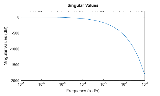
分析该模型的频率响应。
sigmaplot(sys,w)

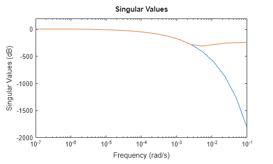
为了获得截断逼近,请使用 zpk 并指定关注的频带。对于此模型,您可以使用 0 弧度/秒到 0.01 弧度/秒的频率范围来获得低阶逼近。
zsys = zpk(sys,Focus=[0 1e-2],Display="off");比较频率响应。
sigmaplot(sys,zsys,w)

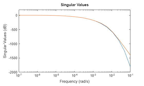
此热模型在超过 0.001 弧度/秒后具有非常陡峭的滚降。默认情况下,使用 zpk 获得的降阶模型在此滚降特性上无法很好地匹配。为了解决这个问题,您可以使用 zpk 的 RollOff 参量,并指定超过关注的频带后的最小滚降值。请指定滚降斜率值为 -45,该值对应于至少 –900 db/十倍频程的速率。
zsys2 = zpk(sys,Focus=[0 1e-2],RollOff=-45,Display="off");
sigmaplot(sys,zsys2,w)
现在,降阶模型对滚降值的逼近效果要好得多。然而,在此示例中,使用 zpk 重新调整滚降斜率需要重新计算零极点。对于大型模型来说,这意味着计算成本可能相当高。作为替代方案,您可以在软件计算零极点完毕后,使用 reducespec 的零极点截断方法并调整滚降,而无需额外的计算成本。有关示例,请参阅Zero-Pole Truncation of Thermal Model。
算法
zpk 使用 MATLAB 函数 roots 转换传递函数,使用函数 zero 和 pole 转换状态空间模型。
为了转换稀疏模型,zpk 使用 Krylov--Schur 算法 [1] 进行逆幂迭代,以计算指定频率带内的零极点。
参考
[1] Stewart, G. W. “A Krylov--Schur Algorithm for Large Eigenproblems.” SIAM Journal on Matrix Analysis and Applications 23, no. 3 (January 2002): 601–14. https://doi.org/10.1137/S0895479800371529.
版本历史记录
在 R2006a 之前推出现在,您可以使用 zpk 来转换稀疏状态空间模型并获得截断零极点增益逼近。zpk 会计算稀疏模型的零极点子集,通常在特定的低频带 [0 fmax] 内。与模态截断模型降阶相比,这种方法虽然会导致更多的计算量,但能得到更好的低频逼近效果。此外,zpk 还允许您直接控制超过频率 fmax 后的滚降斜率。使用新语法 zsys = zpk(sparseSys,Name=Value) 基于指定的选项(例如关注的频率范围)获得逼近。有关示例,请参阅计算稀疏模型的截断 ZPK 逼近。
MATLAB Command
You clicked a link that corresponds to this MATLAB command:
Run the command by entering it in the MATLAB Command Window. Web browsers do not support MATLAB commands.
选择网站
选择网站以获取翻译的可用内容,以及查看当地活动和优惠。根据您的位置,我们建议您选择:。
您也可以从以下列表中选择网站:
如何获得最佳网站性能
选择中国网站(中文或英文)以获得最佳网站性能。其他 MathWorks 国家/地区网站并未针对您所在位置的访问进行优化。
美洲
- América Latina (Español)
- Canada (English)
- United States (English)
欧洲
- Belgium (English)
- Denmark (English)
- Deutschland (Deutsch)
- España (Español)
- Finland (English)
- France (Français)
- Ireland (English)
- Italia (Italiano)
- Luxembourg (English)
- Netherlands (English)
- Norway (English)
- Österreich (Deutsch)
- Portugal (English)
- Sweden (English)
- Switzerland
- United Kingdom (English)