Tune PID
            Controller
Tune PID Controller for LTI plant in the Live Editor
Description
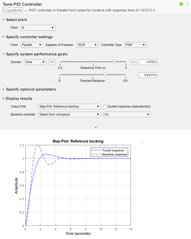
The Tune PID Controller Live Editor task lets you interactively tune a PID controller for a plant. The task automatically generates MATLAB® code for your live script. For more information about Live Editor tasks generally, see Add Interactive Tasks to a Live Script.
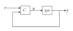
Tune PID Controller automatically tunes the gains of a PID controller for a SISO plant to achieve a balance between performance and robustness. You can specify the controller type, such as PI, PD, or PID with or without a derivative filter. By default, Tune PID Controller assumes the following standard unit-feedback control configuration.

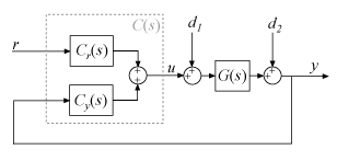
You can also use Tune PID Controller to design a 2-DOF PID controller for the feedback configuration of this illustration:

Tune PID Controller generates analysis plots that let you examine controller performance in the time and frequency domains. You can interactively refine the performance of the controller to adjust response time, loop bandwidth, or phase margin, or to favor setpoint tracking or disturbance rejection.
To get started with the Tune PID Controller task, select the plant model and specify the type of controller you want to design. Experiment with the sliders and observe their effect on the closed-loop system response. For an example, see PID Controller Design in the Live Editor.
Related Functionality
Tune PID Controller generates code using
pidtuneandpidtuneOptions.To perform interactive PID tuning in a standalone app, use PID Tuner.

Open the Task
To add the Tune PID Controller task to a live script in the MATLAB Editor:
On the Live Editor tab, select Task > Tune PID Controller.
In a code block in your script, type a relevant keyword, such as
tuneorPID. SelectTune PID Controllerfrom the suggested command completions.
Parameters
Plant and Controller Settings
Choose a plant for which to design a controller. The list contains continuous-time or discrete-time SISO LTI models present in the MATLAB workspace, such as:
State-space (
ss), transfer function (tf), and zero-pole-gain (zpk) models.For frequency-response data (
frd) models. For such plants, only frequency-domain design goals and response plots are available.Generalized state-space (
genss) or uncertain state-space (uss) models. For such models, Tune PID Controllers uses the current, nominal value of the tunable and uncertain components.Identified models, such as
idssandidtfmodels.
Specify the controller form. The two forms differ in the parameters used to express the proportional, integral, and derivative actions and the filter on the derivative term. For information about parallel and standard forms, see:
By default, Tune PID Controller designs a one-degree-of-freedom (1-DOF) controller. Such a controller has up to four coefficients (see Proportional-Integral-Derivative (PID) Controllers).
You can instead design a two-degree-of-freedom (2-DOF) PID controller. Such controllers include setpoint weighting on the proportional and derivative terms. A 2-DOF PID controller is capable of fast disturbance rejection without significant increase of overshoot in setpoint tracking. You can also use 2-DOF PID controllers to mitigate the influence of changes in the reference signal on the control signal. For more information, see Two-Degree-of-Freedom PID Controllers.
The controller type specifies which terms are present in the PID controller. For instance, a PI controller has a proportional and an integral term. A PDF controller has a proportional term and a filtered derivative term. For details on available controller types, see PID Controller Types for Tuning.
System Performance Goals
Choose the domain in which the task displays the target performance parameters.
Time— Use the sliders to set performance goals in terms of response time and transient behavior. Time-domain tuning is not available for frequency-response data plants such asfrdplants.Frequency— Use the sliders to set performance goals in terms of loop bandwidth and phase margin.
The choice of domain does not affect the underlying controller design or the results. You can use whichever is more convenient for you or more appropriate for your application. For instance, if your design goals include a target rise time, you might find it convenient to work in the time domain. If you have a target loop bandwidth, you might prefer working in the frequency domain. In both domains, there is a trade-off between reference tracking and disturbance rejection performance.
When you set Domain to Time, use
these sliders to adjust the responsiveness and robustness of the controller.
Use the Response Time slider to make the closed-loop response of the control system faster or slower. To change the limits of the slider, drag the slider to the left or right end. To decrease or increase the response time by a factor of 10, click
 or
or  .
.Use the Transient Behavior slider to make the controller more aggressive at disturbance rejection (smaller values) or more robust against plant uncertainty (larger values).
Time-domain tuning is not available for frequency-response data plants such as
frd plants.
When you set Domain to Frequency,
use these sliders to adjust the bandwidth and phase margin of the control system.
Use the Bandwidth slider to make the closed-loop response of the control system faster or slower (the response time is 2/wc, where wc is the bandwidth). To change the limits of the slider, drag the slider to the left or right end. To decrease or increase the bandwidth by a factor of 10, click
 or
or  .
.For discrete-time controllers, Tune PID Controller limits the maximum bandwidth to
pi/Ts, whereTsis the sample time of the selected plant.Use the Phase Margin slider to make the controller more aggressive at disturbance rejection (smaller values) or more robust against plant uncertainty (larger values).
Optional Parameters
For a given target phase margin, Tune PID Controller chooses a controller design that balances the two measures of performance, reference tracking and disturbance rejection. When you change the Design focus option, the tuning algorithm attempts to adjust the PID gains to favor either reference tracking or disturbance rejection while achieving the same target phase margin.
The Design focus options follow:
Balanced— For a given robustness, tune the controller to balance reference tracking and disturbance rejection.
Reference tracking— Tune the controller to favor reference tracking, if possible.
Input disturbance rejection— Tune the controller to favor disturbance rejection, if possible.
The more tunable parameters there are in the system, the more likely it is that the PID algorithm can achieve the desired design focus without sacrificing robustness. For example, setting the design focus is more likely to be effective for PID controllers than for P or PI controllers.
In all cases, how much you can fine-tune the performance of the system depends strongly on the properties of your plant. For some plants, changing the Design Focus option might have little or no effect.
For discrete-time PID controllers, there are different ways to implement the integrator and filter terms. For instance, for a parallel-form discrete-time PID controller, the controller transfer function is
IF(z) and DF(z) are the discrete integrator formulas for the integrator and derivative filter. (To see how IF(z) and DF(z) affect other controller forms, including standard form and 2-DOF controllers, see Discrete-Time Proportional-Integral-Derivative (PID) Controllers.)
Use Integral formula and Filter formula to select the values of IF(z) and DF(z), respectively.
Forward Euler— IF(z) or DF(z) =This formula is best for small sample times, where the Nyquist limit is large compared to the bandwidth of the controller. For larger sample times, the
Forward Eulerformula can result in instability, even when you discretize a system that is stable in continuous time.Backward Euler— IF(z) or DF(z) =An advantage of the
Backward Eulerformula is that discretizing a stable continuous-time system using this formula always yields a stable discrete-time result.Trapezoidal— IF(z) or DF(z) =An advantage of the
Trapezoidalformula is that discretizing a stable continuous-time system using this method always yields a stable discrete-time result. Of all available discrete integrator formulas,Trapezoidalyields the closest match between the frequency-domain properties of the discretized system and the corresponding continuous-time system.
Display
Specify a response plot for observing the effect of the PID controller on system performance. You can specify a time-domain step response plot or a frequency-domain Bode plot for different system responses. The code that Tune PID Controller generates in your live script includes code for generating the plot you select.
Available System Responses
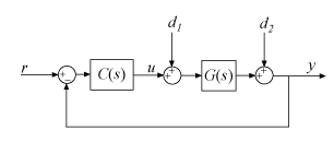
For 1-DOF PID controller types such as PI, PIDF, and PDF, the software computes system responses based upon the following single-loop control architecture, where G is your specified plant and C is the PID controller:

For 2-DOF PID controller types such as PI2, PIDF2, and I-PD, the software computes responses based upon the following architecture:

The system responses are based on the decomposition of the 2-DOF PID controller, C, into a setpoint component Cr and a feedback component Cy, as described in Two-Degree-of-Freedom PID Controllers.
The following table summarizes the available responses for analysis plots. (For frequency-response-data plants such as frd
models, time-domain response plots are not available.)
| Response | Plotted System (1-DOF) | Plotted System (2-DOF) | Description |
|---|---|---|---|
Plant | G | G | Plant response. Use to examine plant dynamics. |
Open-loop | GC | –GCy | Response of the open-loop controller-plant system. Use for frequency-domain design. Use when your design specifications include robustness criteria such as open-loop gain margin and phase margin. |
Reference tracking | (from r to y) | (from r to y) | Closed-loop system response to a step change in setpoint. Use when your design specifications include setpoint tracking. |
Controller effort | (from r to u) | (from r to u) | Closed-loop controller output response to a step change in setpoint. Use when your design is limited by practical constraints, such as controller saturation. |
Input disturbance rejection | (from d1 to y) | (from d1 to y) | Closed-loop system response to load disturbance (a step disturbance at the plant input). Use when your design specifications include input disturbance rejection. |
Output disturbance rejection | (from d2 to y) | (from d2 to y) | Closed-loop system response to a step disturbance at plant output. Use when you want to analyze sensitivity to modeling errors. |
Select this option to generate a display of numeric characteristics of the closed-loop or open-loop response.
When Output Plot is a step plot, the display includes characteristics such as rise time, settling time, and percent overshoot. These values are always those of the closed-loop step response from the control system input r to output y, regardless of which specific step response you choose for the plot. Tune PID Controller uses
stepinfoto compute the step-response characteristics. For details about how to interpret these values, see thestepinforeference page.When Output Plot is a Bode plot, the display includes characteristics such as gain margin and phase margin. These values are always those of the open-loop system response GC, regardless of which specific Bode plot you choose. Tune PID Controller uses
allmarginto compute the frequency-response characteristics. For details about how to interpret these values, see theallmarginreference page.
Use this option when you want to compare the performance of the tuned controller to
another PID controller in the MATLAB workspace. To do so, choose Select from
workspace. Another menu appears containing PID model objects that are
currently in the workspace. The list includes PID model objects of all types
(pid, pidstd, pid2, or
pidstd2) that are of the same time domain as the currently specified
plant. For instance, if the plant is a discrete-time state-space model, then any
discrete-time PID model object in the workspace is available as a baseline
controller.
When you specify a baseline controller, the response plot updates to include a dotted-line plot of the system response with the baseline controller.

Store Controller for Comparison
You can store a design to use as a baseline while you experiment further with controller types, performance goals, and other settings. To do so, when you find the design that you want to use as a baseline:
Note the name of the controller workspace variable in the task summary line (see Tips). For instance, if the name is
C, then the current controller is in the MATLAB workspace asC.Change the name of the controller variable in the task summary line. For instance, change it to
Cnew.Select Baseline Controller and specify the stored controller
Cas the baseline.When you experiment further with the controller design, the task stores changes to the controller in the workspace as
Cnew. The plot shows you the baseline response usingCand the tuned response usingCnew.
Tips
After you select a plant, the task creates the controller and stores it in the MATLAB workspace. The stored controller is a
pid,pidstd,pid2, orpidstd2model object, as specified by your selections for Form and Degrees of Freedom.The default variable name for the stored controller is
C. You can change the variable name by typing a new name into the task summary line.
The task also provides information about the performance and robustness of the closed-loop system in a structure called
pidInfoby default. For information about this structure, see theinfooutput argument on thepidtunereference page.
Algorithms
Tune PID Controller uses the algorithm discussed in PID Tuning Algorithm.
Version History
Introduced in R2019b
See Also
Apps
Functions
Objects
MATLAB Command
You clicked a link that corresponds to this MATLAB command:
Run the command by entering it in the MATLAB Command Window. Web browsers do not support MATLAB commands.
选择网站
选择网站以获取翻译的可用内容,以及查看当地活动和优惠。根据您的位置,我们建议您选择:。
您也可以从以下列表中选择网站:
如何获得最佳网站性能
选择中国网站(中文或英文)以获得最佳网站性能。其他 MathWorks 国家/地区网站并未针对您所在位置的访问进行优化。
美洲
- América Latina (Español)
- Canada (English)
- United States (English)
欧洲
- Belgium (English)
- Denmark (English)
- Deutschland (Deutsch)
- España (Español)
- Finland (English)
- France (Français)
- Ireland (English)
- Italia (Italiano)
- Luxembourg (English)
- Netherlands (English)
- Norway (English)
- Österreich (Deutsch)
- Portugal (English)
- Sweden (English)
- Switzerland
- United Kingdom (English)