Generate Code for Battery State of Charge Estimation Using Deep Learning
This example shows how to generate code for battery state of charge (SOC) estimation.
SOC is the level of charge of an electric battery relative to its capacity, measured as a percentage. This example shows how to perform software-in-the-loop (SIL) testing of the battery state of charge model.

This example is in a series of examples that take you through a battery state of charge estimation workflow. You can run each step independently or work through the steps in order. This example follows the Integrate AI Model into Simulink for Battery State of Charge Estimation example. For more information about the full workflow, see Battery State of Charge Estimation Using Deep Learning.
Load Trained Network
If you have run the previous steps, then the example uses the network that you trained. Otherwise, the example loads a network trained as in Train Deep Learning Network for Battery State of Charge Estimation and compressed in Compress Deep Learning Network for Battery State of Charge Estimation.
if ~exist("recurrentNet","var")
    load("pretrainedBSOCNetworkCompressed.mat")
end
The network has been trained to predict battery SOC given three inputs: temperature, voltage, and current. The network has been trained on data taken at four different ambient temperatures: -10, 0, 10, and 25 degrees Celsius.
Open Simulink Model
Open a Simulink® model for battery state of charge estimation. This model contains a subsystem with an AI component. In this example, the AI component is a trained LSTM network that can predict the state of charge given temperature, voltage, and current inputs.
open_system("BatterySOCEstimationDeepLearning")Prepare the test data using the prepareSimulinkBSOCTestData function, attached to this example as a supporting file. This function prepares the data as shown in the Integrate AI Model into Simulink for Battery State of Charge Estimation example.
[steps,Ts,ds] = prepareSimulinkBSOCTestData;
set_param("BatterySOCEstimationDeepLearning", ...
    StopTime="steps", ...
    LoadExternalInput="on", ...
    ExternalInput="ds", ...
    FixedStep="Ts")
SIL Simulation
A SIL simulation generates source code from the model, compiles and builds the source code, and executes an application as a separate process on your host computer. By comparing normal and SIL simulation results, you can test the numerical equivalence of your model and the generated code. During a SIL simulation, you can collect code coverage and execution-time metrics for the generated code.
On the Apps tab, click SIL/PIL Manager.

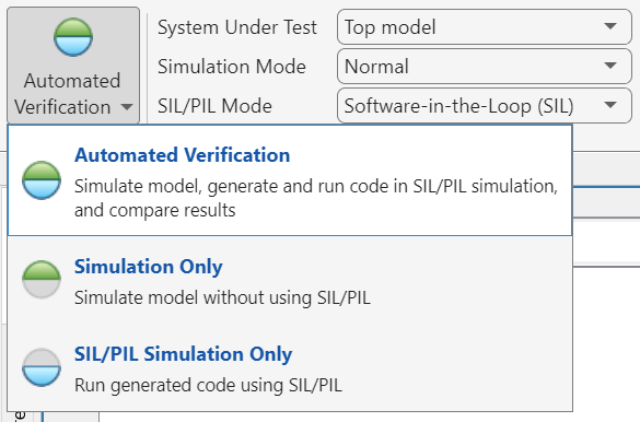
In the Mode section, select Automated Verification.

In the Prepare section, set System Under Test to Top model. In the SIL/PIL Mode field, select Software-in-the-Loop (SIL).

Click Run Verification.
View Results
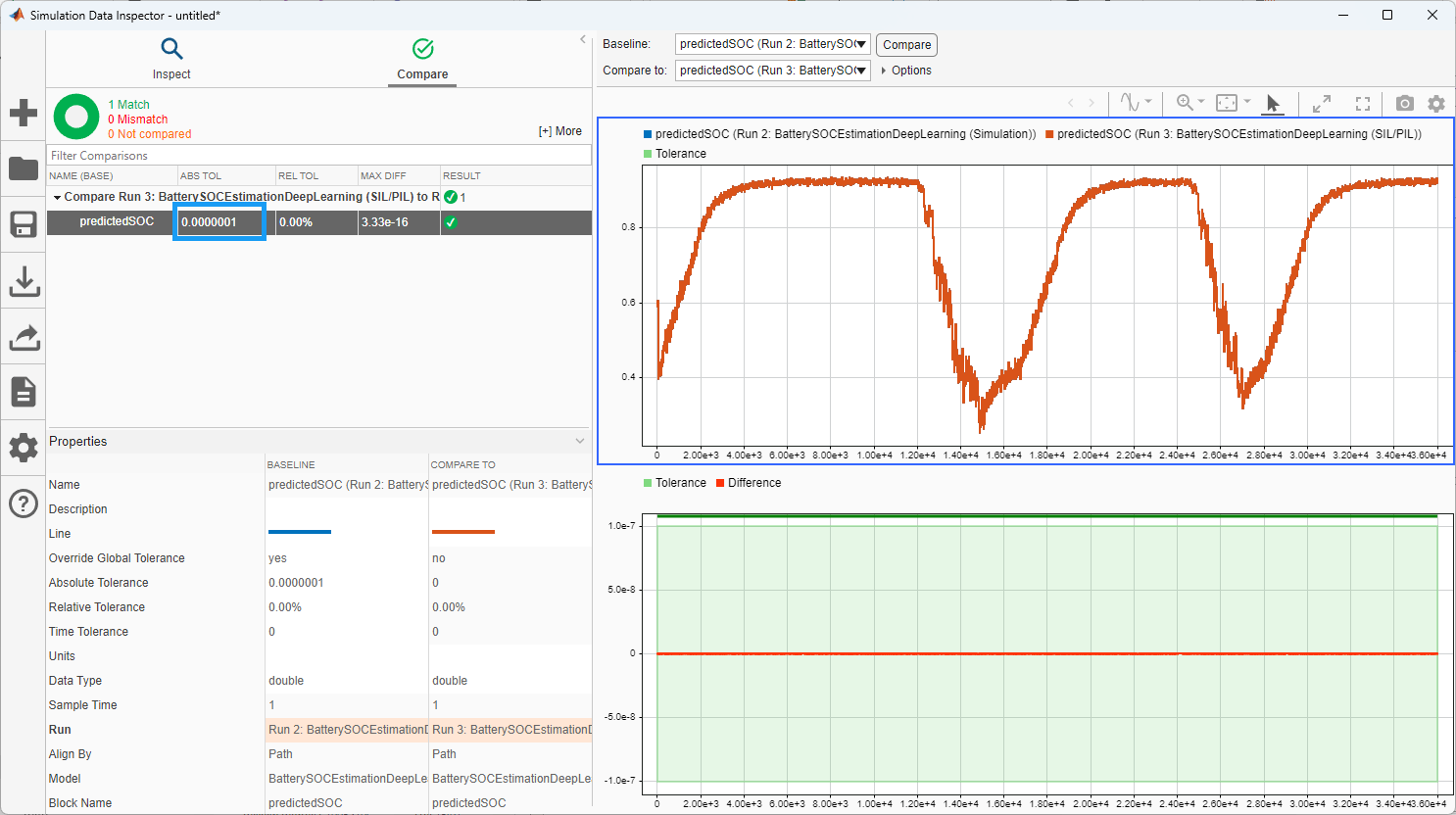
At the end of the simulation, the Data Inspector opens and compares the Simulation and SIL results. In the table, set ABS TOL to 1e-7. This setting specifies the allowable difference between the signals from the simulation and the generated code. The maximum absolute difference between the simulation and generated code signals for the predicted SOC is very low.

Trace Simulink Model Elements in Generated Code
Code tracing (traceability) uses hyperlinks to navigate between a line of generated code and its corresponding elements in a model. You can use this to trace which parts of the code related to each layer.
To trace the generated code to blocks in the Simulink model:
Open the model
Open the Embedded Coder® app. Build the model. On the C Code tab, click Build.The HTML code generation report opens by default. To use the report, see Code Generation Report.
View the generated code in the Code view in the Code perspective. The source code contains traceability information such as hyperlinked comments, line numbers, variables, and operators.
In the model element, click a layer block.
In the generated code in the Code view window, you see the first instance of highlighted code that is generated for the layer block. At the top of the Code view, numbers that appear to the right of generated file names indicate the total number of highlighted lines in each file. This figure shows the result of tracing the Sigmoid Layer block in the
BatterySOCEstimationDeepLearningmodel.

Link SIL Requirements Using Requirements Toolbox
This section verifies the SIL testing requirements and requires Requirements Toolbox™ and Simulink® Test™. This section does not show how to create or link requirements, only how to implement and verify the links. For more information about defining these requirements, see Define Requirements for Battery State of Charge Estimation. For general information about how to create and manage requirements, see Use Requirements to Develop and Verify MATLAB Functions (Requirements Toolbox).
Linking SIL testing requirements is important for ensuring the AI model behaves as expected once you have generated code.
Check for a Requirements Toolbox™ license.
if ~license("test","simulink_requirements")
    disp("This part of the example requires Requirements Toolbox.");
    return
end
Open the SIL requirements. To add columns that indicate the implementation status and verification status of the requirements, click Columns ![]() and then select Implementation Status and Verification Status. If you see a yellow banner, then click Analyze now. You can see each of the requirements and their implementation status and verification status. The verification status for each requirement is yellow, indicating that the status is unknown. The status turns to red if the requirement fails or green if the requirement passes.
and then select Implementation Status and Verification Status. If you see a yellow banner, then click Analyze now. You can see each of the requirements and their implementation status and verification status. The verification status for each requirement is yellow, indicating that the status is unknown. The status turns to red if the requirement fails or green if the requirement passes.
slreq.open("BatterySOCReqCodeGen.slreqx");
load_system("BatterySOCEstimationDeepLearning.slx")
sltest.testmanager.load("BSOCSimulinkIntegrationTestSIL.mldatx");

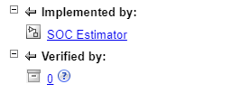
Select one of the requirements. Each requirement is implemented by the SOC Estimator subsystem and verified by a test.

Implement Requirements
SIL testing ensures that the generated code for the model behaves as expected. For example, you can test numerical equivalence between the model and generated code.
Verify Requirements
The next step is to formally verify the requirements. To verify requirements, create tests to check the SIL results. You can find the SIL tests in the BSOCSimulinkIntegrationTestSIL file, attached to this example as a supporting file. To verify the requirements, create tests that check that for each temperature, the difference between the Simulink and SIL simulation values is within a certain tolerance.

Before you can run SIL from the test, you must first generate code for the top model. To build the model and general code, follow the previous steps or use Ctrl+B in the Simulink canvas.
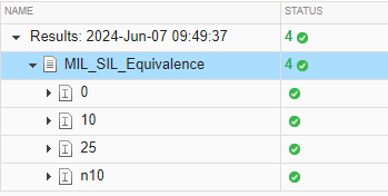
To run the tests, open Test Manager with BSOCSimulinkIntegrationTestSIL. Select MIL_SIL_Equivalence. This test checks that the SIL simulation and the Simulink model are within 1e-7 of each other. To run the test, click Run.
The test passes for each temperature. You can adjust the threshold to match the requirement of your system.

In Requirements Editor, you can see that the verification status is now green (Passed).

See Also
Requirements Editor (Requirements Toolbox)