Create 360° Bird's-Eye-View Image Around a Vehicle
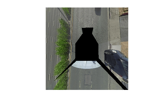
R2026bThis example shows how to create a 360° bird's-eye-view image around a vehicle for use in a surround view monitoring system. It then shows how to generate code for the same bird's-eye-view image creation algorithm and verify the results.
Overview
Surround view monitoring is an important safety feature provided by advanced driver-assistance systems (ADAS). These monitoring systems reduce blind spots and help drivers understand the relative position of their vehicle with respect to the surroundings, making tight parking maneuvers easier and safer. A typical surround view monitoring system consists of multiple cameras mounted on the four sides of the vehicle. A display in the vehicle shows the driver the front, left, right, rear, and bird's-eye view of the vehicle. While multiple views from the cameras are trivial to display, creating a bird's-eye view of the vehicle surroundings requires intrinsic and extrinsic camera calibration and image stitching to combine the multiple camera views.
In this example, you first learn how to calibrate a multi-camera system mounted on a vehicle. You then use the calibrated cameras to create a bird's-eye-view image of the surroundings by stitching together images from multiple cameras.
Calibrate Multi-Camera System on Vehicle
Calibrating a multi-camera system on a vehicle involves three steps: estimating camera intrinsics, calibrating the extrinsic relationships between cameras, and positioning one of the cameras relative to the vehicle coordinate system.
Calibrate Camera Intrinsics
Camera intrinsic calibration estimates parameters such as focal length, principal point, and lens distortion coefficients for each camera. These parameters are required for removing distortion, measuring real-world distances, and generating the bird's-eye-view image. Calibrate each camera individually using the Using the Single Camera Calibrator App app. After calibration, export the camera parameters to the workspace and save the intrinsics for each camera.
Calibrate Multi-Camera Extrinsics
After obtaining intrinsics for each camera, calibrate the extrinsic relationships between all cameras using the Multi-Camera Calibrator app. This app estimates the rigid transforms between camera pairs, enabling you to express all cameras in a common coordinate frame. Because cameras on a vehicle typically share very narrow overlapping fields of view, it is recommended to use multiple calibration patterns such as ChArUco boards or AprilGrid to collect calibration data. For detailed instructions on capturing calibration images for a multi-camera setup, see Data Collection Guidelines for Multi-Camera Calibration.
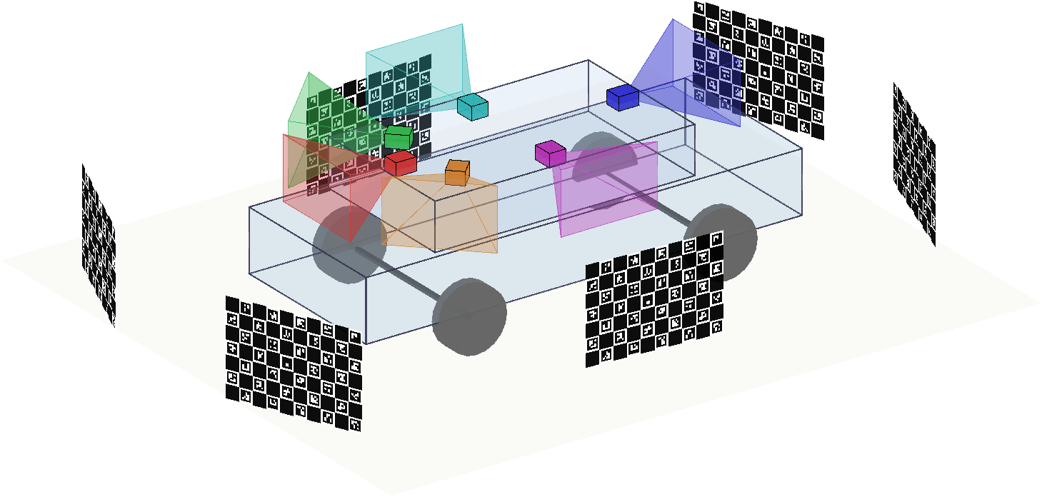
After calibration, export the calibration results to the workspace. The result is a multiCameraParameters object containing the relative extrinsics between all cameras.
Calibrate Camera-to-Vehicle Transform
The multi-camera calibration from the previous step establishes relative transforms between cameras, but does not position the cameras in the vehicle coordinate system. To anchor the camera rig to the vehicle, estimate the extrinsics of the reference camera relative to the vehicle using the estimateMonoCameraParameters function. Estimating the extrinsics involves capturing a calibration pattern from the reference camera in a specific orientation with respect to the road and the vehicle. For details on the camera extrinsics estimation process and pattern orientation, see Calibrate Monocular Camera Mounted on a Vehicle.
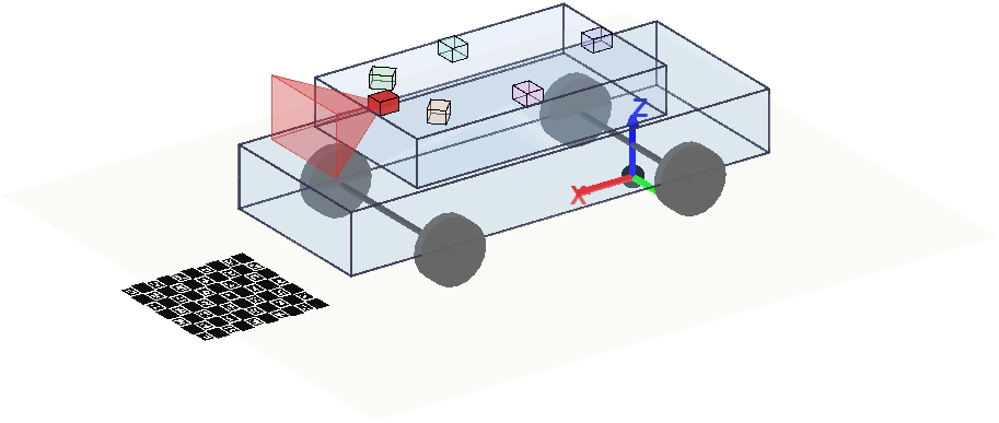
Once you know the mounting angles and location of the reference camera in the vehicle frame, use changeReferenceFrame to express all camera poses in the vehicle coordinate system. Create a separate multiSensorParameters object with the reference camera's mounting pose in the vehicle frame, then combine it with the multi-camera calibration results through the common sensor. The following example code shows how to do this:
% Get all camera poses in the reference camera frame from the multiCameraParameters object
camPoses = multiCameraParams.CameraPoses;
camNames = "Camera" + (1:multiCameraParams.NumCameras);

% Convert translations from calibration pattern units (millimeters) to meters
for i = 1:numel(camPoses)
    camPoses(i).Translation = camPoses(i).Translation / 1000;
end

% Get camera intrinsics
camIntrinsics = multiCameraParams.Intrinsics;

% Create a multiSensorParameters object using the calibrated camera mounting poses
multiSensorParam = multiSensorParameters(ReferenceFrame=camNames(1));
multiSensorParam = addSensor(multiSensorParam, camNames, "camera", camPoses, Intrinsics=camIntrinsics);

% Create a multiSensorParameters object with Camera1's mounting pose in the
% vehicle frame. roll, pitch, yaw, and height are outputs of
% estimateMonoCameraParameters. xOffset and yOffset are the measured
% longitudinal and lateral offsets of the camera from the vehicle coordinate
% origin (rear axle ground point), in meters.
vehicleObj = multiSensorParameters(ReferenceFrame="vehicle");
vehicleObj = addSensor(vehicleObj, camNames(1), "camera", ...
    [yaw, pitch, roll], [xOffset, yOffset, height], Intrinsics=camIntrinsics(1));

% Combine via the common sensor (Camera1) to express all camera poses
% in the vehicle coordinate system.
multiSensorParam = combine(vehicleObj, multiSensorParam);
Store the final calibration results in a multiSensorParameters object for use in subsequent processing steps. For more details about sensor calibration, see What Is Multi-Sensor Calibration??
Next, you will use a calibrated multi-camera system to create a surround bird's-eye-view image.
Load and Visualize Image Data
Download a zip file containing camera image data. The data used is from the PandaSet dataset. The sensor rig contains six cameras and two lidars, but this example uses only the camera images.
dataFolder = tempdir;
dataFileName = "PandasetLidarCameraData.zip";
url = "https://ssd.mathworks.com/supportfiles/driving/data/" + dataFileName;
filePath = fullfile(dataFolder, dataFileName);
if ~isfile(filePath)
    websave(filePath, url);
end
unzip(filePath, dataFolder);
imageFolder = fullfile(dataFolder, "PandasetLidarCameraData", "camera");
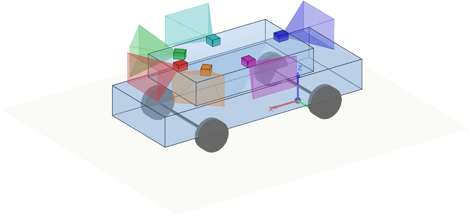
Load the multi-sensor parameters and create a subset containing only the cameras. Visualize the camera mounting poses in the vehicle coordinate system.
multiSensorObj = load("multiSensorObjPandaSet.mat").multiSensorObj;
multiCamObj = subset(multiSensorObj, "camera");

plot(multiCamObj);
hold off
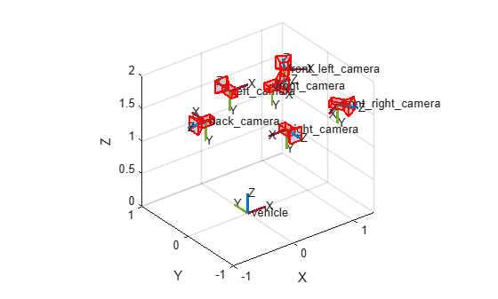
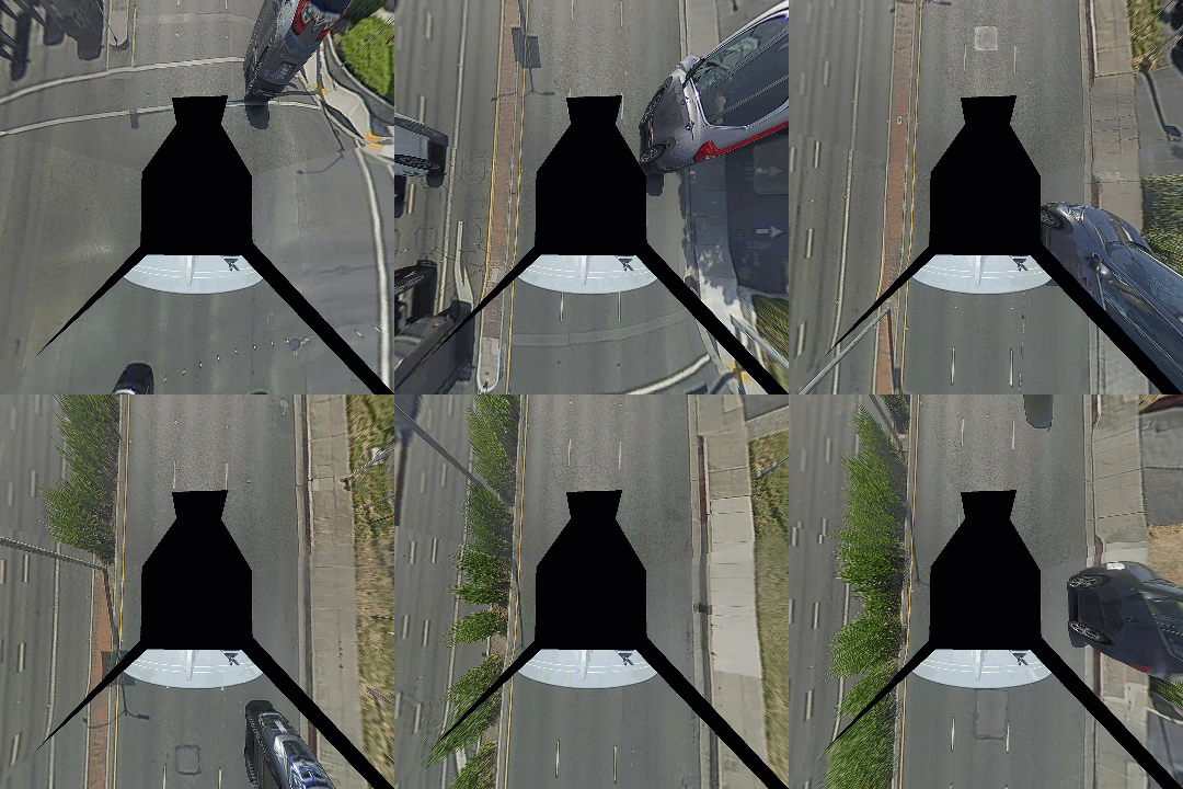
Read and display the first set of images from the six cameras. If the images contain lens distortion, remove it before proceeding. The images in this dataset have already been undistorted.
cameraNames = multiCamObj.Sensors.Name;
numCameras  = multiCamObj.Count;
camIntrinsics = intrinsics(multiCamObj);
frameIndex = 1;
imageGrid  = cell(1, numCameras);

figure(Position=[0 0 1200 450])
tiledlayout(2, 3);
for camIdx = 1:numCameras
    nexttile;
    I = imread(fullfile(imageFolder, cameraNames(camIdx), sprintf('%02d.jpg', frameIndex)));
    imshow(I);
    title(cameraNames(camIdx), Interpreter="none");

    % If images contain lens distortion, use undistortImage to remove
    % lens distortion:
    % I = undistortImage(I, camIntrinsics{camIdx});
    imageGrid{camIdx} = I;
end
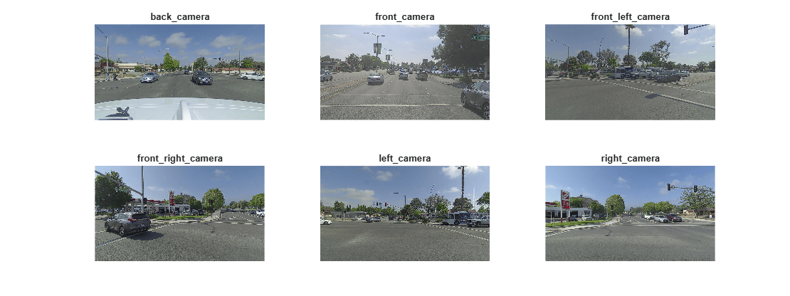
Create Bird's-Eye-View Objects for Each Camera
Create a birdsEyeView object for each camera. This requires constructing a yolov4ObjectDetectorMonoCamera object from each camera's intrinsics and mounting pose stored in the multiSensorParameters object. The yaw angle of each camera is also stored for later use in cropping the invalid half of the bird's-eye-view image.
% Define the output area as a square region centered on the vehicle.
distFromVehicle = 12; % meters
outView = [-distFromVehicle, distFromVehicle, ... % [xmin, xmax,
    -distFromVehicle, distFromVehicle];   %  ymin, ymax]

% Use the same output image size for all cameras so the BEV images can be
% merged directly. Setting one dimension to NaN preserves the aspect ratio.
bevImageSize = [size(I, 2), NaN];

birdsEye = cell(1, numCameras);
cameraYaw = zeros(1, numCameras);

for camIdx = 1:numCameras
    camName = cameraNames(camIdx);

    camIntrinsics = intrinsics(multiCamObj, camName);
    [mountingAngles, mountingLocation] = mountingPose(multiCamObj, camName);

    % Store yaw angle for determining the crop direction later.
    cameraYaw(camIdx) = mountingAngles(1);

    monoCam = monoCamera(camIntrinsics, mountingLocation(3), ...
        Yaw=mountingAngles(1), Pitch=mountingAngles(2), Roll=mountingAngles(3), ...
        SensorLocation=mountingLocation(1:2));

    birdsEye{camIdx} = birdsEyeView(monoCam, outView, bevImageSize);
end
Transform and Stitch Multi-Camera Images
Project each camera image onto the ground plane using transformImage. After projection, each BEV image covers the full square output area, but the half of the image that falls behind the camera contains reflected artifacts from the inverse perspective mapping. Crop this invalid half based on the camera's facing direction.
bevSize = birdsEye{1}.ImageSize;
halfSize = round(bevSize(1) / 2);

bevImgs = cell(1, numCameras);
for camIdx = 1:numCameras
    bevImgs{camIdx} = transformImage(birdsEye{camIdx}, imageGrid{camIdx});

    % Zero out the half of the BEV image behind the camera. The facing
    % direction is determined by the camera yaw angle in the vehicle frame.
    bevImgs{camIdx} = helperCropBehindCamera(bevImgs{camIdx}, ...
        cameraYaw(camIdx), halfSize);
end
Blend all six BEV images into a single surround view. In overlapping regions, the pixel closer to its own image center is preferred, producing a seamless stitch.
surroundingView = zeros(bevSize(1), bevSize(2), 3, "uint8");
for camIdx = 1:numCameras
    surroundingView = helperBlendImages(surroundingView, bevImgs{camIdx});
end

figure
imshow(surroundingView);
title("surround Bird's-Eye View");
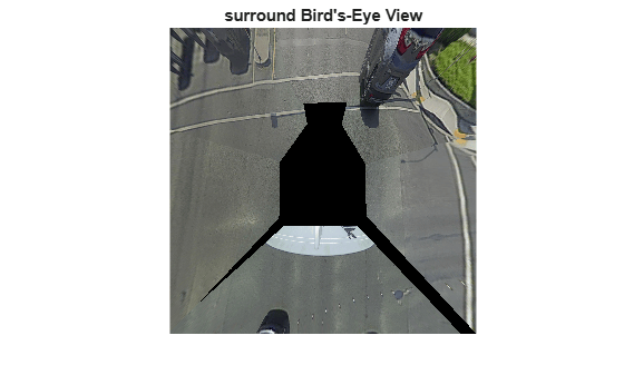
Create Surround View for All Frames
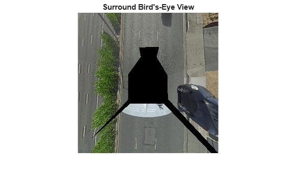
The single-frame code above has been packaged into a helper function, helperCreateSurroundingView, to process all frames in a loop.
figure
hImg = imshow(surroundingView);
title("Surround Bird's-Eye View");

numFrames = 80;
for frameIndex = 1:numFrames
    imageGrid = cell(1, numCameras);
    for camIdx = 1:numCameras
        imageGrid{camIdx} = imread(fullfile(imageFolder, ...
            cameraNames(camIdx), sprintf('%02d.jpg', frameIndex)));
    end
    surroundingView = helperCreateSurroundingView(birdsEye, imageGrid, bevSize);

    hImg.CData = surroundingView;
    drawnow limitrate
end
Code Generation
This algorithm can be deployed in hardware. To meet the requirements of MATLAB Coder, the above code is restructured to the entry-point function helperCreateSurroundingViewCodegen. The function takes an array of birdsEyeView structures and a cell array of images as inputs and outputs the surround view. Because code generation does not support arrays of birdsEyeView objects, they need to be converted to an array of structures using the helperToStructBev function.
birdsEyeStructs = arrayfun(@(i) helperToStructBev(birdsEye{i}), 1:numCameras);Use the codegen function to compile the helperCreateSurroundingViewCodegen function into a MEX file. You can specify the -report option to generate a compilation report that shows the original MATLAB code and the associated files created during code generation. You can also create a temporary directory where MATLAB Coder can store the generated files. Note that, by default, the generated MEX file has the same name as the original MATLAB function with "_mex" appended as a suffix: helperCreateSurroundingViewCodegen_mex. Alternatively, you can use the -o option to specify the name of the MEX file.
cpuConfig = coder.config("mex");
cpuConfig.TargetLang = "C++";
codegen -config cpuConfig helperCreateSurroundingViewCodegen -args {birdsEyeStructs,imageGrid,bevSize}
Code generation successful.
Process the image data using the MEX file and show the surround views.
surroundingView = helperCreateSurroundingViewCodegen_mex(birdsEyeStructs, imageGrid, bevSize);
imshow(surroundingView);
Helper Functions
helperCreateSurroundingView - Create a stitched surround BEV image.
helperCropBehindCamera - Zero out the BEV half behind a camera.
helperBlendImages - Blend two images using distance-to-edge weighting.
helperCreateSurroundingViewCodegen - Code-generation-compatible version of helperCreateSurroundingView.
helperToStructBev - Converts the specified birdsEyeView objects to structure format.
helperToObjectBev - Creates birdsEyeView objects from the parameters specified in a structure format.
See Also
Apps
Functions
undistortImage|estimateMonoCameraParameters|detectKAZEFeatures|matchFeatures|matchFeaturesInRadius|estgeotform3d

