Create Driving Scenario Interactively and Generate Synthetic Sensor Data
This example shows how to create a driving scenario and generate vision and radar sensor detections from the scenario by using the Driving Scenario Designer app. You can use this synthetic data to test your controllers or sensor fusion algorithms.
This example shows the entire workflow for creating a scenario and generating synthetic sensor data. Alternatively, you can generate sensor data from prebuilt scenarios. See Prebuilt Driving Scenarios in Driving Scenario Designer.
Create Driving Scenario
To open the app, at the MATLAB® command prompt, enter drivingScenarioDesigner.
Add a Road
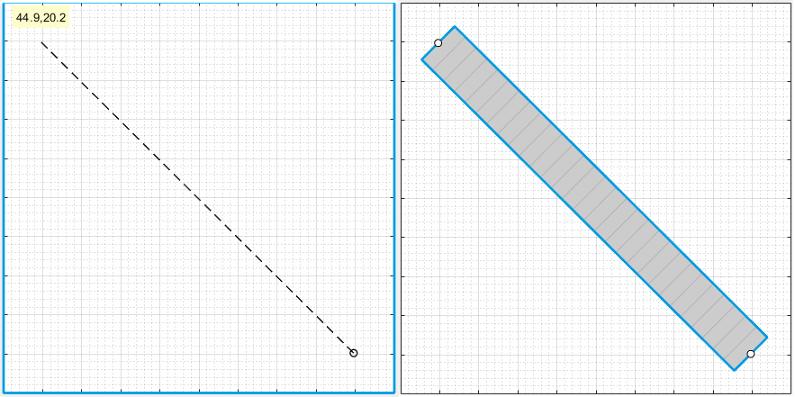
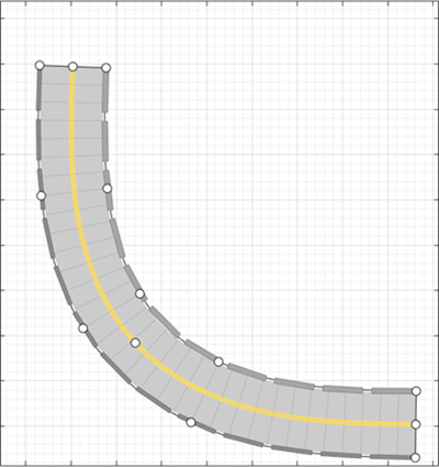
Add a curved road to the scenario canvas. On the app toolstrip, click Add Road. Then click one corner of the canvas, extend the road to the opposite corner, and double-click the canvas to create the road.
To make the road curve, add a road center around which to curve it. Right-click the middle of the road and select Add Road Center. Then drag the added road center to one of the empty corners of the canvas.
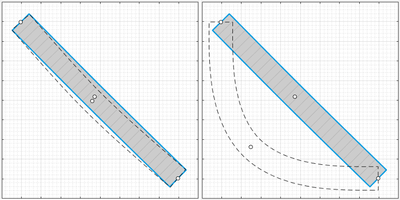
To adjust the road further, you can click and drag any of the road centers. To create more complex curves, add more road centers.
Add Lanes
By default, the road is a single lane and has no lane markings. To make the scenario
more realistic, convert the road into a two-lane highway. In the left pane, on the
Roads tab, expand the Lanes section. Set
the Number of lanes to [1 1]. The app sets
the Lane Width parameter to 3.6 meters,
which is a typical highway lane width.
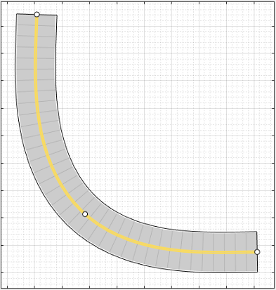
The white, solid lanes markings on either edge of the road indicate the road shoulder. The yellow, double-solid lane marking in the center indicates that the road is a two-way road. To inspect or modify these lanes, from the Lane Marking list, select one of the lanes and modify the lane parameters.
Add Barriers
To add barriers along the edges of the curved road, use the app toolstrip or the road context menu. On the app toolstrip, click Add Actor > Jersey Barrier. Move the cursor to the right edge of the road and click to add a barrier along it. This also opens up the Barriers tab on the left pane. To add a gap of 1m between the barrier segments change the value of the Segment Gap (m) property in the Barriers tab to 1.
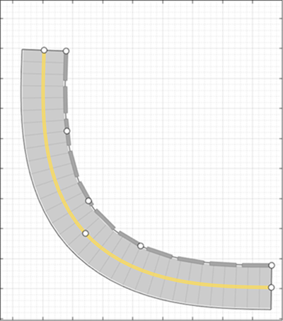
To add a guardrail barrier to the left edge of the road using the road context menu, right click on the road and select Add Guardrail > Left edge. Specify a 1m gap between the barrier segments for the guardrail, using the Segment Gap (m) property in the Barriers tab.
Add Vehicles
By default, the first car that you add to a scenario is the ego vehicle, which is the main car in the driving scenario. The ego vehicle contains the sensors that detect the lane markings, pedestrians, or other cars in the scenario. Add the ego vehicle, and then add a second car for the ego vehicle to detect.
Add Ego Vehicle
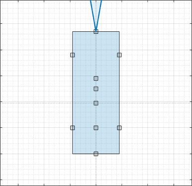
To add the ego vehicle, right-click one end of the road, and select Add Car. To specify the trajectory of the car, right-click the car, select Add Waypoints, and add waypoints along the road for the car to pass through. After you add the last waypoint along the road, press Enter. The car autorotates in the direction of the first waypoint. For finer precision over the trajectory, you can adjust the waypoints. You can also right-click the path to add new waypoints.
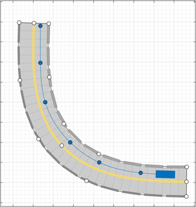
The triangle indicates the pose of the vehicle, with the origin located at the center of the rear axle of the vehicle.
Adjust the speed of the car. In the left pane, on the Actors
tab, set Constant Speed to 15 m/s. For
more control over the speed of the car, set the velocity between waypoints in the
v (m/s) column of the Waypoints, Speeds, Wait
Times, and Yaw table.
Add Second Car
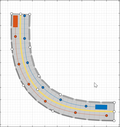
Add a vehicle for the ego vehicle sensors to detect. On the app toolstrip, click Add Actor and select Car. Add the second car with waypoints, driving in the lane opposite from the ego vehicle and on the other end of the road. Leave the speed and other settings of the car unchanged.
Add a Pedestrian
Add to the scenario, a pedestrian crossing the road. Zoom in on the middle of the road, right-click one side of the road, and click Add Pedestrian. Then, to set the path of the pedestrian, add a waypoint on the other side of the road.

By default, the color of the pedestrian nearly matches the color of the lane markings. To make the pedestrian stand out more, from the Actors tab, click the corresponding color patch for the pedestrian to modify its color.
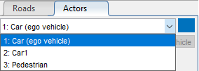
To test the speed of the cars and the pedestrian, run the simulation. Adjust actor speeds or other properties as needed by selecting the actor from the left pane of the Actors tab.
For example, if the cars are colliding with the pedestrian, in the v (m/s) column of the Waypoints, Speeds, Wait Times, and Yaw table, adjust the speeds of the cars or the pedestrian. Alternatively, in the wait (s) column of the table, set a wait time for the cars at the waypoint before the pedestrian crosses the street.
By default, the simulation ends when the first actor completes its trajectory. To end
the simulation only after all actors complete their trajectories, on the app toolstrip,
first click Settings. Then, set Stop Condition
to Last actor stops.
Add Sensors
Add camera, radar, and lidar sensors to the ego vehicle. Use these sensors to generate detections and point cloud data from the scenario.
Add Camera
On the app toolstrip, click Add Camera. The sensor canvas shows standard locations at which to place sensors. Click the frontmost predefined sensor location to add a camera sensor to the front bumper of the ego vehicle.
To place sensors more precisely, you can disable snapping options. In the
bottom-left corner of the sensor canvas, click the Configure the Sensor Canvas
button ![]() .
.
By default, the camera detects only actors and not lanes. To enable lane
detections, on the Sensors tab in the left pane, expand the
Detection Parameters section and set Detection
Type to Objects & Lanes. Then expand
the Lane Settings section and update the settings as
needed.
Add Radars
Snap a radar sensor to the front-left wheel. Right-click the predefined sensor location for the wheel and select Add Radar. By default, sensors added to the wheels are short-range sensors.
Tilt the radar sensor toward the front of the car. Move your cursor over the coverage area, then click and drag the angle marking.
Add an identical radar sensor to the front-right wheel. Right-click the sensor on the front-left wheel and click Copy. Then right-click the predefined sensor location for the front-right wheel and click Paste. The orientation of the copied sensor mirrors the orientation of the sensor on the opposite wheel.

Add Lidar
Snap a lidar sensor to the center of the roof of the vehicle. Right-click the predefined sensor location for the roof center and select Add Lidar.

The lidar sensor appears in black. The gray surrounding the vehicle is the coverage area of the sensor. Zoom out to see the full view of the coverage areas for the different sensors.

Generate Synthetic Sensor Data
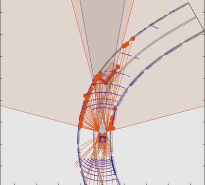
To generate data from the sensors, click Run. As the scenario runs, The Bird’s-Eye Plot displays the detections and point cloud data.
The Ego-Centric View displays the scenario from the perspective of the ego vehicle.
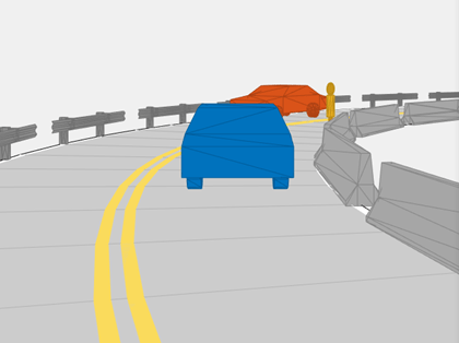
Because you specified a lidar sensor, both the Ego-Centric View and Bird's-Eye Plot display the mesh representations of actors instead of the cuboid representations. The lidar sensors use these more detailed representations of actors to generate point cloud data. The Scenario Canvas still displays only the cuboid representations. The radar and vision sensors base their detections on the cuboid representations.
To turn off actor meshes, certain types of detections, or other aspects of the displays, use the properties under Display on the app toolstrip.
By default, the scenario ends when the first actor stops moving. To run the scenario for a set amount of time, on the app toolstrip, click Settings and change the stop condition.
Next, export the sensor detection:
To export sensor data to the MATLAB workspace, on the app toolstrip, select Export > Export Sensor Data. Name the workspace variable and click OK. The app saves the sensor data as a structure containing sensor data such as the actor poses, object detections, and lane detections at each time step.
To export a MATLAB function that generates the scenario and its sensor data, select Export > Export MATLAB Function. This function returns the sensor data as a structure, the scenario as a
drivingScenarioobject, and the sensor models as System objects. By modifying this function, you can create variations of the original scenario. For an example of this process, see Create Driving Scenario Variations Programmatically.
Save Scenario
After you generate the detections, click Save to save the scenario file. You can also save the sensor models as separate files and save the road and actor models together as a separate scenario file.
You can reopen this scenario file from the app. Alternatively, at the MATLAB command prompt, you can use this syntax.
drivingScenarioDesigner(scenarioFileName)
drivingScenario object. At the MATLAB command prompt, use this syntax, where scenario is the name of
the exported
object.drivingScenarioDesigner(scenario)
sensors is a sensor object or a cell
array of such
objects.drivingScenarioDesigner(scenario,sensors)
drivingScenario object
into your model. This block does not directly read sensor data. To add sensors that you created
in the app to a Simulink model, generate a model containing your scenario and sensors by selecting Export > Export Simulink Model. In the model, the generated Scenario Reader block reads the
scenario and the generated sensor blocks define the sensors.See Also
Apps
Blocks
- Scenario Reader | Driving Radar Data Generator | Vision Detection Generator | Lidar Point Cloud Generator
Objects
drivingScenario|drivingRadarDataGenerator|visionDetectionGenerator|lidarPointCloudGenerator|insSensor
Topics
- Keyboard Shortcuts and Mouse Actions for Driving Scenario Designer
- Create Roads with Multiple Lane Specifications Using Driving Scenario Designer
- Create Reverse Motion Driving Scenarios Interactively
- Prebuilt Driving Scenarios in Driving Scenario Designer
- Create Driving Scenario Variations Programmatically
- Test Open-Loop ADAS Algorithm Using Driving Scenario
- Test Closed-Loop ADAS Algorithm Using Driving Scenario