Generate Code for Highway Lane Following Controller
This example shows how to test the highway lane following controller and generate C++ code for real-time applications on a prebuilt 3D scene from the Unreal Engine® driving simulation environment.
In this example, you:
Design a test bench model to verify the functionality of a lane following decision logic and controller with ground truth information.
Generate code for the lane following decision logic and controller, and validate the functional equivalence by using software-in-the-loop (SIL) simulation.
Introduction
The lane following controller is a fundamental component in highway lane following applications. The lane following controller generates the steering angle and acceleration control commands for an ego vehicle by using lane and vehicle information along with the set speed.
The lane following controller combines longitudinal and lateral controls. The longitudinal controller is responsible for maintaining the driver-set velocity and keeping a safe distance from the lead vehicle. The lateral controller is responsible for keeping the vehicle in the center of its current lane. In this example, you use the ground truth lane and vehicle information to test the lane following controller. For more information, see Path Following Control System (Model Predictive Control Toolbox).
This example shows how to test and verify the functionality of a lane following controller using a 3D simulation environment. In this example, you:
Explore the test bench model.
Simulate the test bench model.
Generate C++ code from the reference model.
Assess the functionality of the generated code using SIL verification.
Assess the execution time and perform code coverage analysis.
Explore additional scenarios given in this example.
You test the lane following controller on a 3D simulation environment that uses the Unreal Engine from Epic Games®.
if ~ispc
    error(['This example is supported only on Microsoft', char(174), ' Windows', char(174), '.'])
end
Explore Test Bench Model
To explore the test bench model, load the highway lane following controller project.
openProject("HLFController");
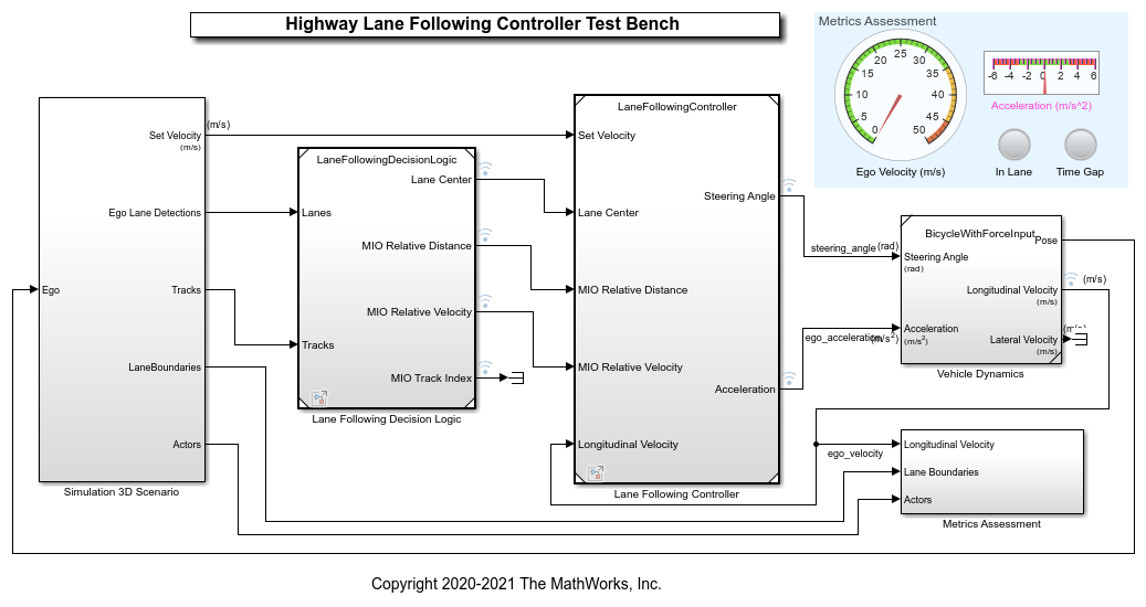
In this example, you use a system-level simulation test bench model to explore the behavior of the controller for the lane following system. Open the system-level simulation test bench model.
open_system('HighwayLaneFollowingControllerTestBench');

Opening this model runs the helperSLHighwayLaneFollowingControllerSetup script, which initializes the road scenario using the drivingScenario object in the base workspace. It also configures the lane following controller parameters, vehicle model parameters, and Simulink bus signals required for defining the inputs and outputs for the HighwayLaneFollowingControllerTestBench model.
The test bench model contains these subsystems:
Simulation 3D Scenario — This subsystem specifies the road, vehicles used for simulation.
Lane Following Decision Logic — This subsystem specifies the lateral and longitudinal decision logic.
Lane Following Controller — This subsystem specifies the path-following controller that generates control commands to steer the ego vehicle.
Vehicle Dynamics — This subsystem specifies the dynamic model for the ego vehicle.
Metrics Assessment — This subsystem specifies metrics to assess system level behavior.
The Vehicle Dynamics subsystem is the same subsystem used in the Highway Lane Following example. This example focuses on the Lane Following Decision Logic and Lane Following Controller reference models.
The Simulation 3D Scenario subsystem configures the road network, sets vehicle positions, and packs truth data, similar to the Simulation 3D Scenario subsystem in the Highway Lane Following. However, the Simulation 3D Scenario subsystem used in this example does not have any sensors. Instead, lanes truth from the Simulation 3D Vision Detection Generator block is packed into lanes bus and actors truth from Scenario Reader block is packed into tracks bus structure to provide inputs to the lane following decision logic. Open the Simulation 3D Scenario subsystem.
open_system('HighwayLaneFollowingControllerTestBench/Simulation 3D Scenario');

The Pack Actors Truth MATLAB® function block packs the ground truth information of the actors into the tracker bus structure, which the Lane Following Decision Logic reference model requires.
The Simulation 3D Vision Detection Generator block is attached to the ego vehicle to get lane truth information from the 3D simulation environment.
The Pack Lanes Truth MATLAB function block packs the lane ground truth information into the lanes bus structure, which the Lane Following Decision Logic reference model requires.
The Rear Axle to Vehicle Center block shifts the lane detections from rear axle to the vehicle center as required by the lateral controller.
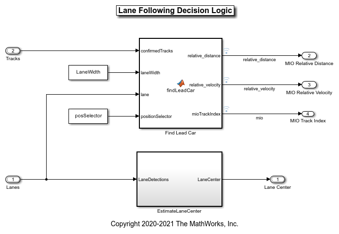
Lane Following Decision Logic is the reference model that detects the lead vehicle information and lane center. The Lane Following Controller model needs this information. Open Lane Following Decision Logic model.
open_system('LaneFollowingDecisionLogic');

The Find Lead Car MATLAB function block finds the lead car that is most important object (MIO) present in front of the ego vehicle in the same lane. It outputs the relative distance and relative velocity between the ego vehicle and the MIO.
The Estimate Lane Center subsystem calculates the lane center of the ego lane, which is required by the Lane Following Controller model.
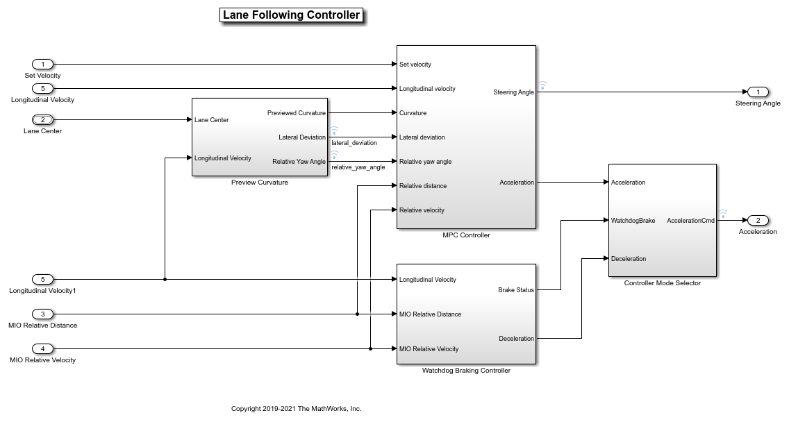
The Lane Following Controller takes as input the MIO information and lane center information from the lane following decision logic reference model, along with the set velocity and longitudinal velocity of ego vehicle. The model then generates control commands (steering angle and acceleration) for the ego vehicle. Open the Lane Following Controller model.
open_system('LaneFollowingController');

The Preview Curvature block calculates the curvature, lateral deviation, and relative yaw angle using the lane center information. The controller uses previewed information for calculating the ego vehicle steering angle. The lateral deviation measures the distance between the ego vehicle and the center of the lane. The relative yaw angle measures the yaw angle difference between the ego vehicle and the road. The ISO 8855 to SAE J670E block inside subsystem converts the lane coordinates from the ISO 8855 standard to the SAE J670E standard used by MPC Controller.
The MPC Controller block uses the Path Following Control System (Model Predictive Control Toolbox) block from Model Predictive Control Toolbox™. The Path Following Controller block keeps the vehicle traveling within a marked lane of a highway while maintaining the driver-set velocity. This controller includes combined longitudinal and lateral control of the ego vehicle:
Longitudinal control maintains the driver-set velocity of the ego vehicle.
Lateral control keeps the ego vehicle traveling along the center line of its lane by adjusting the steering angle of the ego vehicle.
The MPC controller provides a slow and steady response to the ego vehicle. A faster response is required during the emergency conditions, and the Watchdog Braking Controller block applies the brakes under such conditions.
Based on the braking status of the Watchdog Braking Controller block, the Controller Mode Selector subsystem outputs the acceleration command that determines whether to accelerate or decelerate.
Simulate Model
Configure the HighwayLaneFollowingControllerTestBench model to simulate the scenario_LFACC_03_Curve_StopnGo scenario. This scenario contains six vehicles, including the ego vehicle, and defines their trajectories.
helperSLHighwayLaneFollowingControllerSetup("scenarioFcnName", "scenario_LFACC_03_Curve_StopnGo");
Simulate the test bench model.
sim('HighwayLaneFollowingControllerTestBench');
   Assuming no disturbance added to measured output #3.
-->Assuming output disturbance added to measured output #2 is integrated white noise.
   Assuming no disturbance added to measured output #1.
-->Assuming output disturbance added to measured output #4 is integrated white noise.
-->"Model.Noise" is empty. Assuming white noise on each measured output.
Generate C++ Code
You can now generate C++ code for the algorithm, apply common optimizations, and generate a report to facilitate exploring the generated code. Configure the Lane Following Decision Logic and Lane Following Controller models to generate C++ code for real-time implementation of the algorithm. Set the model parameters to enable code generation and display the configuration values.
Set and view model parameters to enable C++ code generation.
helperSetModelParametersForCodeGeneration('LaneFollowingController');
save_system('LaneFollowingController');
 Model  configuration parameters:

                 Parameter                      Value                                                              Description
    ___________________________________    _______________    ______________________________________________________________________________________________________________________

    {'SystemTargetFile'               }    {'ert.tlc'    }    {'Code Generation>System target file'                                                                                }
    {'TargetLang'                     }    {'C++'        }    {'Code Generation>Language'                                                                                          }
    {'SolverType'                     }    {'Fixed-step' }    {'Solver>Type'                                                                                                       }
    {'FixedStep'                      }    {'auto'       }    {'Solver>Fixed-step size (fundamental sample time)'                                                                  }
    {'EnableMultiTasking'             }    {'on'         }    {'Solver>Treat each discrete rate as a separate task'                                                                }
    {'ProdLongLongMode'               }    {'on'         }    {'Hardware Implementation>Support long long'                                                                         }
    {'BlockReduction'                 }    {'on'         }    {'Simulation Target>Block reduction'                                                                                 }
    {'MATLABDynamicMemAlloc'          }    {'on'         }    {'Simulation Target>Simulation Target>Dynamic memory allocation in MATLAB functions'                                 }
    {'OptimizeBlockIOStorage'         }    {'on'         }    {'Simulation Target>Signal storage reuse'                                                                            }
    {'InlineInvariantSignals'         }    {'on'         }    {'Simulation Target>Inline invariant signals'                                                                        }
    {'BuildConfiguration'             }    {'Faster Runs'}    {'Code Generation>Build configuration'                                                                               }
    {'RTWVerbose'                     }    {'off'        }    {'Code Generation>Verbose build'                                                                                     }
    {'CombineSignalStateStructs'      }    {'on'         }    {'Code Generation>Interface>Combine signal/state structures'                                                         }
    {'SupportVariableSizeSignals'     }    {'on'         }    {'Code Generation>Interface>Support variable-size signals'                                                           }
    {'CodeInterfacePackaging'         }    {'C++ class'  }    {'Code Generation>Interface>Code interface packaging'                                                                }
    {'GenerateExternalIOAccessMethods'}    {'Method'     }    {'Code Generation>Interface>Data Member Visibility>External I/O access'                                              }
    {'EfficientFloat2IntCast'         }    {'on'         }    {'Code Generation>Optimization>Remove code from floating-point to integer conversions that wraps out-of-range values'}
    {'ZeroExternalMemoryAtStartup'    }    {'off'        }    {'Code Generation>Optimization>Remove root level I/O zero initialization (inverse logic)'                            }
    {'CustomSymbolStrGlobalVar'       }    {'$N$M'       }    {'Code Generation>Symbols>Global variables'                                                                          }
    {'CustomSymbolStrType'            }    {'$N$M_T'     }    {'Code Generation>Symbols>Global types'                                                                              }
    {'CustomSymbolStrField'           }    {'$N$M'       }    {'Code Generation>Symbols>Field name of global types'                                                                }
    {'CustomSymbolStrFcn'             }    {'APV_$N$M$F' }    {'Code Generation>Symbols>Subsystem methods'                                                                         }
    {'CustomSymbolStrTmpVar'          }    {'$N$M'       }    {'Code Generation>Symbols>Local temporary variables'                                                                 }
    {'CustomSymbolStrMacro'           }    {'$N$M'       }    {'Code Generation>Symbols>Constant macros'                                                                           }
Generate code and review the code generation report from the reference model.
slbuild('LaneFollowingController');
### Starting build procedure for: LaneFollowingController
   Assuming no disturbance added to measured output #3.
-->Assuming output disturbance added to measured output #2 is integrated white noise.
   Assuming no disturbance added to measured output #1.
-->Assuming output disturbance added to measured output #4 is integrated white noise.
-->"Model.Noise" is empty. Assuming white noise on each measured output.
### Successful completion of build procedure for: LaneFollowingController

Build Summary

Top model targets:

Model                    Build Reason                                         Status
============================================================================================================
LaneFollowingController  Information cache folder or artifacts were missing.  Code generated and compiled.

1 of 1 models built (0 models already up to date)
Build duration: 0h 1m 1.7558s
Assess Functionality of Code
After generating the C++ code, you can now assess the code functionality using SIL simulation. Simulation provides early insight into the behavior of a deployed application. To learn more about SIL simulation, see SIL and PIL Simulations (Embedded Coder).
SIL simulation enables you to verify that the compiled generated code on the host is functionally equivalent to the normal mode.
Configure the reference model parameters to support SIL simulation and log the execution profiling information.
helperSetModelParametersForSIL('LaneFollowingController');
helperSetModelParametersForSIL('HighwayLaneFollowingControllerTestBench');
LaneFollowingController configuration parameters:

               Parameter                       Value                                    Description
    ________________________________    ____________________    ____________________________________________________________

    {'SystemTargetFile'            }    {'ert.tlc'         }    {'Code Generation>System target file'                      }
    {'TargetLang'                  }    {'C++'             }    {'Code Generation>Language'                                }
    {'CodeExecutionProfiling'      }    {'on'              }    {'Code Generation>Verification>Measure task execution time'}
    {'CodeProfilingSaveOptions'    }    {'AllData'         }    {'Code Generation>Verification>Save options'               }
    {'CodeExecutionProfileVariable'}    {'executionProfile'}    {'Code Generation>Verification>Workspace variable'         }


HighwayLaneFollowingControllerTestBench configuration parameters:

               Parameter                       Value                                    Description
    ________________________________    ____________________    ____________________________________________________________

    {'SystemTargetFile'            }    {'ert.tlc'         }    {'Code Generation>System target file'                      }
    {'TargetLang'                  }    {'C++'             }    {'Code Generation>Language'                                }
    {'CodeExecutionProfiling'      }    {'on'              }    {'Code Generation>Verification>Measure task execution time'}
    {'CodeProfilingSaveOptions'    }    {'AllData'         }    {'Code Generation>Verification>Save options'               }
    {'CodeExecutionProfileVariable'}    {'executionProfile'}    {'Code Generation>Verification>Workspace variable'         }
Configure the test bench model to simulate Lane Following Decision Logic and Lane Following Controller in SIL mode.
set_param('HighwayLaneFollowingControllerTestBench/Lane Following Controller','SimulationMode','Software-in-the-loop (SIL)');

sim('HighwayLaneFollowingControllerTestBench');
### Searching for referenced models in model 'HighwayLaneFollowingControllerTestBench'.
### Found 1 model reference targets to update.
### Starting serial model reference code generation build.
### Starting build procedure for: LaneFollowingController
   Assuming no disturbance added to measured output #3.
-->Assuming output disturbance added to measured output #2 is integrated white noise.
   Assuming no disturbance added to measured output #1.
-->Assuming output disturbance added to measured output #4 is integrated white noise.
-->"Model.Noise" is empty. Assuming white noise on each measured output.
### Successful completion of build procedure for: LaneFollowingController

Build Summary

Model reference code generation targets:

Model                    Build Reason                                         Status
============================================================================================================
LaneFollowingController  Target (LaneFollowingController.cpp) did not exist.  Code generated and compiled.

1 of 1 models built (0 models already up to date)
Build duration: 0h 1m 3.4384s
### Preparing to start SIL simulation ...
Building with 'Microsoft Visual C++ 2019 (C)'.
MEX completed successfully.
### Starting SIL simulation for component: LaneFollowingController
### Application stopped
### Stopping SIL simulation for component: LaneFollowingController
Compare the outputs from normal simulation mode and SIL simulation mode. You can verify if the differences between these runs are in the tolerance limits by using the following code. Plot the differences of the steering and acceleration values between the normal simulation mode and SIL simulation mode.
runIDs = Simulink.sdi.getAllRunIDs;
normalSimRunID = runIDs(end - 1);
SilSimRunID = runIDs(end);
diffResult = Simulink.sdi.compareRuns(normalSimRunID ,SilSimRunID);
Plot the differences in the controller output parameters computed from normal mode and SIL mode.
helperPlotLFControllerDiffSignals(diffResult);

The differences between the normal and SIL modes of the simulation are approximately zero. Slight differences are due to differences in the rounding off techniques used by different compilers.
Assess Execution Time and Coverage of Code
During the SIL simulation, log the execution time metrics for the generated code on the host computer to the variable executionProfile in the MATLAB base workspace. These times can be an early indicator of the performance of the generated code. For accurate execution time measurements, profile the generated code when it is integrated into the external environment or when you use with processor-in-the-loop (PIL) simulation. To learn more about PIL profiling, refer to Create Execution-Time Profile for Generated Code (Embedded Coder).
Plot the execution time taken for _step function using the helperPlotLFControllerExecutionProfile function.
helperPlotLFControllerExecutionProfile(executionProfile);

From the plot, you can deduce the average time taken per timestep for the lane following controller. For more information on generating execution profiles and analyzing them during SIL simulation, refer to Execution Time Profiling for SIL and PIL (Embedded Coder).
If you have a Simulink Coverage™ license, you can also perform the code coverage analysis for the generated code to measure the testing completeness. You can use missing coverage data to find gaps in testing, missing requirements, or unintended functionality. Configure the coverage settings and simulate the test bench model to generate the coverage analysis report. Find the generated report CoverageResults/LaneFollowingController_modelrefsil_summary_cov.html in the working directory.
if(license('test','Simulink_Coverage'))
    helperCoverageSettings('HighwayLaneFollowingControllerTestBench');
    cvDataGroupObj = cvsim('HighwayLaneFollowingControllerTestBench');
    % Get Generated Code coverage of LaneFollowingController.
    cvDataObj = get(cvDataGroupObj,'LaneFollowingController');
    cvhtml('CoverageResults/LaneFollowingController_modelrefsil_summary_cov',cvDataObj);
end
### Searching for referenced models in model 'HighwayLaneFollowingControllerTestBench'.
### Found 1 model reference targets to update.
### Starting serial model reference code generation build.
### Starting build procedure for: LaneFollowingController
   Assuming no disturbance added to measured output #3.
-->Assuming output disturbance added to measured output #2 is integrated white noise.
   Assuming no disturbance added to measured output #1.
-->Assuming output disturbance added to measured output #4 is integrated white noise.
-->"Model.Noise" is empty. Assuming white noise on each measured output.
### Successful completion of build procedure for: LaneFollowingController

Build Summary

Model reference code generation targets:

Model                    Build Reason                            Status
===============================================================================================
LaneFollowingController  Code instrumentation settings changed.  Code generated and compiled.

1 of 1 models built (0 models already up to date)
Build duration: 0h 1m 29.608s
### Preparing to start SIL simulation ...
Building with 'Microsoft Visual C++ 2019 (C)'.
MEX completed successfully.
### Starting SIL simulation for component: LaneFollowingController
### Application stopped
### Stopping SIL simulation for component: LaneFollowingController
### Completed code coverage analysis
You can find the decision coverage, statement coverage, and function coverage results while simulating the generated code for this test scenario, scenario_LFACC_03_Curve_StopnGo. You can test this model with different scenarios to get full coverage of the generated code. For more information on how to analyze coverage results during SIL simulation, refer Code Coverage for Models in Software-in-the-Loop (SIL) Mode and Processor-in-the-Loop (PIL) Mode (Embedded Coder).
Similarly, you can configure Lane Following Decision Logic to generate code and run in SIL to verify the functional equivalence with simulation.
Explore Additional Scenarios
This example provides additional scenarios that you can use with the HighwayLaneFollowingControllerTestBench model:
scenario_LF_01_Straight_RightLane
scenario_LF_02_Straight_LeftLane
scenario_LF_03_Curve_LeftLane
scenario_LF_04_Curve_RightLane
scenario_LFACC_01_Curve_DecelTarget
scenario_LFACC_02_Curve_AutoRetarget
scenario_LFACC_03_Curve_StopnGo [Default]
scenario_LFACC_04_Curve_CutInOut
scenario_LFACC_05_Curve_CutInOut_TooClose
scenario_LFACC_06_Straight_StopandGoLeadCar
scenario_ACC_01_Straight_TargetDiscriminationTest
scenario_ACC_02_Straight_StopnGo
Examine the comments in each file for more details about the geometry of the road and vehicles in each scenario. You can configure the HighwayLaneFollowingControllerTestBench model and workspace to simulate these scenarios using the helperSLHighwayLaneFollowingSetup function as follows.
helperSLHighwayLaneFollowingControllerSetup("scenarioFcnName", "scenario_LFACC_04_Curve_CutInOut");
See Also
Scenario Reader | Vehicle To World | Simulation 3D Scene Configuration | Cuboid To 3D Simulation
Topics
- Automate Testing for Highway Lane Following Controller
- Automate Testing for Highway Lane Following Controls and Sensor Fusion
- Generate Code for Lane Marker Detector
- Generate Code for Vision Vehicle Detector
- Generate C++ Message Interfaces for Lane Following Controls and Sensor Fusion
- Highway Lane Following
- Lane Following Control with Sensor Fusion and Lane Detection