针对信号处理模型配置 Simulink 环境
关于 DSP Simulink 模型模板
通过 DSP Simulink® 模型模板,您可以使用推荐的设置自动配置 Simulink 环境,以用于数字信号处理建模。DSP Simulink 模型模板让您可以重用设置,包括配置参数。您可以从模板创建模型,这些模板使用最佳做法并利用以前的常见问题解决方案。请不要选择新模型的默认画布,而要选择模板模型来帮助您开始。
有关 Simulink 模型模板的详细信息,请参阅从模型创建模板 (Simulink)。
使用 DSP System Toolbox Simulink 模型模板创建模型
要创建一个新的空白模型并打开库浏览器,请执行以下操作:
在 MATLAB® 的主页选项卡的文件部分中,点击新建 > Simulink 模型。Simulink 起始页将打开,其中提供内置的 Simulink 模型模板。
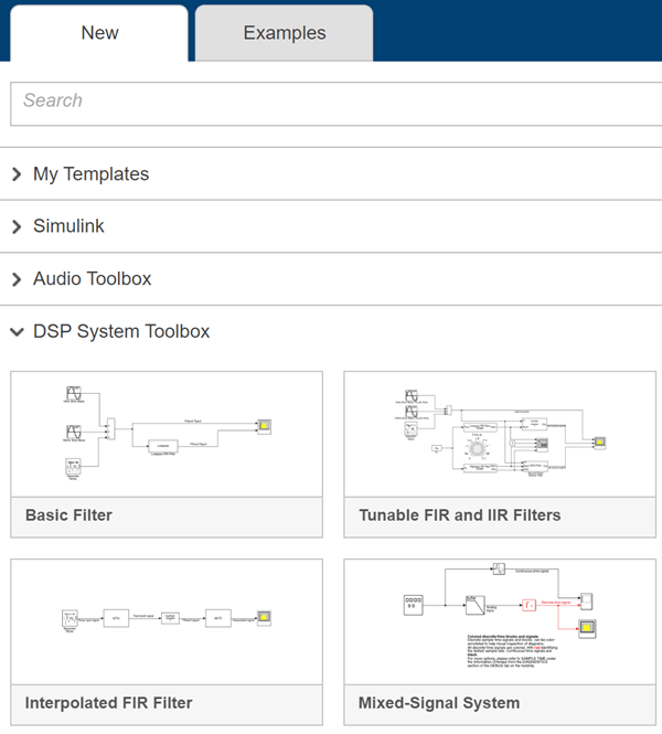
点击 DSP System Toolbox 下的模板之一,创建一个具有适用于 DSP System Toolbox™ 的设置的模型。此时,使用模板设置和内容的新模型将显示在 Simulink 编辑器中。在保存之前,该模型只存在于内存中。
要访问库浏览器,请点击模型工具条上的库浏览器。
DSP Simulink 模型模板
当您通过选择 DSP Simulink 模型模板之一来创建一个模型时,模型配置为使用针对 DSP System Toolbox 推荐的设置。下表显示其中一些设置。
| 配置参数 | 设置 |
|---|---|
| SingleTaskRateTransMsg | error |
| multiTaskRateTransMsg | error |
| Solver | fixedstepdiscrete |
| EnableMultiTasking | Off |
| StartTime | 0.0 |
| StopTime | inf |
| FixedStep | auto |
| SaveTime | off |
| SaveOutput | off |
| AlgebraicLoopMsg | error |
| SignalLogging | off |
| FrameProcessingCompatibilityMsg | error |
以下是 DSP System Toolbox 中的 Simulink 模型模板:
基本滤波器
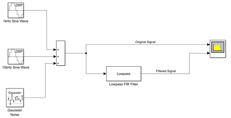
点击基本滤波器以创建一个基本滤波模型,该模型使用针对 DSP System Toolbox 推荐的设置进行配置。
此模型实现一个低通滤波器,使您能够对滤波后的信号与原始信号进行比较。您可以在 Simulink 中基于该模型使用 DSP System Toolbox 对滤波算法进行建模。
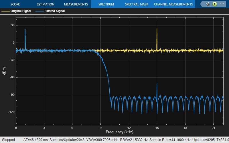
下面是频谱分析仪的输出,该输出显示原始信号和滤波后的信号。输入信号包含 1 kHz 和 15 kHz 的音调。1 kHz 音调通过了滤波后的输出,而 15 kHz 音调发生了衰减。
可调 FIR 和 IIR 滤波器
使用可调 FIR 和 IIR 滤波器模板,设计和实现具有可调滤波器设定的 FIR 和 IIR 滤波器。
此模型显示如何使用 Lowpass FIR Filter Design 和 Lowpass IIR Filter Design 设计模块设计 FIR 和 IIR 滤波器。您可以使用 Knob (Simulink) 模块调节滤波器截止频率。在仿真过程中,设计的滤波器的幅值响应会随着您对滤波器截止频率的调节而变化。使用 Filter Visualizer 模块可视化设计的滤波器的幅值响应。与基本滤波器模型模板一样,输入是具有 1 kHz 和 15 kHz 音调的含噪正弦信号。
Discrete FIR Filter (Simulink) 模块和 Second-Order Section Filter 模块使用来自设计模块的系数实现低通 FIR 滤波器和高通 IIR 滤波器。

滤波器可视化工具输出显示 FIR 滤波器和 IIR 滤波器的变化幅值响应,而频谱分析仪输出显示原始信号和滤波后的信号的频谱。在频谱分析仪输出中,两个音调都发生了衰减。1 kHz 音调被 IIR 滤波器衰减,15 kHz 音调被 FIR 滤波器衰减。

插值 FIR 滤波器
插值 FIR 滤波器模板是单级高阶 FIR 滤波器的高效替代方案,因为它以较低的采样率对信号进行滤波。这种实现可对输入信号进行多级处理。含噪输入首先通过 FIR 抽取器,这会降低信号的采样率。然后,信号由 FIR 滤波器以较低的采样率进行滤波。末端的 FIR 插值器将滤波输出的采样率转换回原始值。

模型中的 Spectrum Analyzer 模块显示滤波后的信号的频谱。
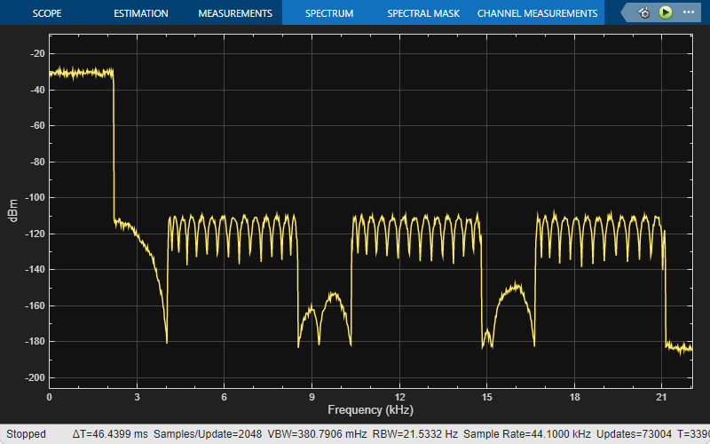
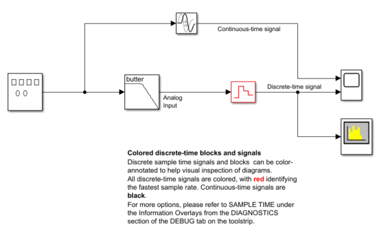
混合信号系统
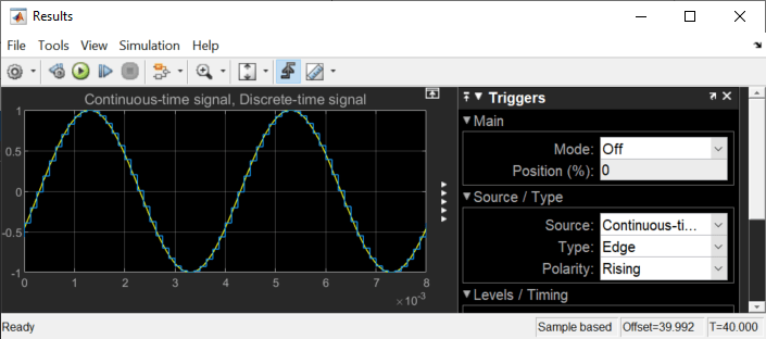
点击混合信号系统模板可创建一个基本模数转换器模型,该模型使用针对 DSP System Toolbox 和混合信号系统推荐的设置进行配置。此模型通过先后实现一个模拟抗混叠滤波器和一个零阶保持电路来执行模数转换。您可以基于该模型使用 DSP System Toolbox 在 Simulink 中进行混合信号系统建模。所有离散时间信号都显示为红色,以表示最快的采样率。连续时间信号显示为黑色。对于其他采样时间选项,请在调试选项卡中,选择叠加信息 > 颜色。
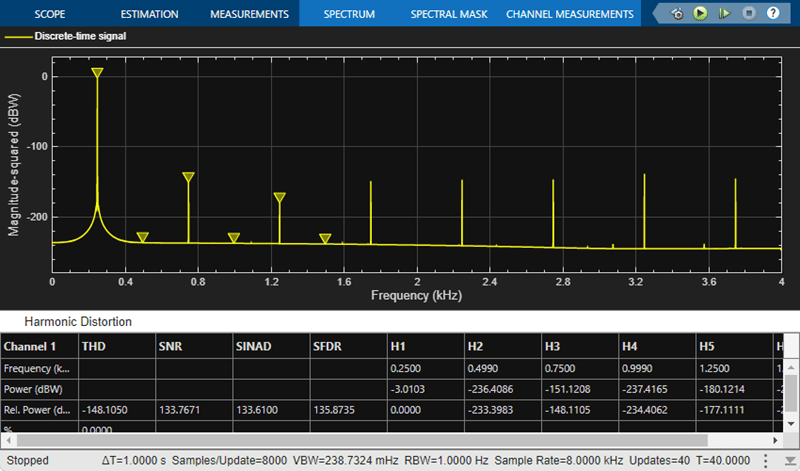
模型中的 Scope (Simulink) 模块绘制连续时间信号和离散时间信号。
Spectrum Analyzer 模块显示离散时间信号的频谱。