Second-Order Section Filter
Libraries:
DSP System Toolbox /
Filtering /
Filter Implementations
Description
The Second-Order Section Filter block implements a cascade of second-order section (SOS) filters in Simulink®. You can specify the numerator and denominator coefficients of the filter in the block parameters dialog box or through input ports.
Examples
Filter a noisy sinusoidal signal using the Second-Order Section Filter block. Obtain the numerator and denominator coefficients of the SOS filter using the Bandpass IIR Filter Design block.
Tune the frequency specifications of the SOS filter during simulation.
Open and Run Model
Open the secondordersectionfilter model.
The input signal in the model is a sum of two sine waves with the frequencies of 100 Hz and 350 Hz. The sample rate is 1000 Hz and the number of samples in each frame is 1024. The Random Source block adds zero-mean white Gaussian noise with a variance of 1e-4 to the sum of the sine waves.
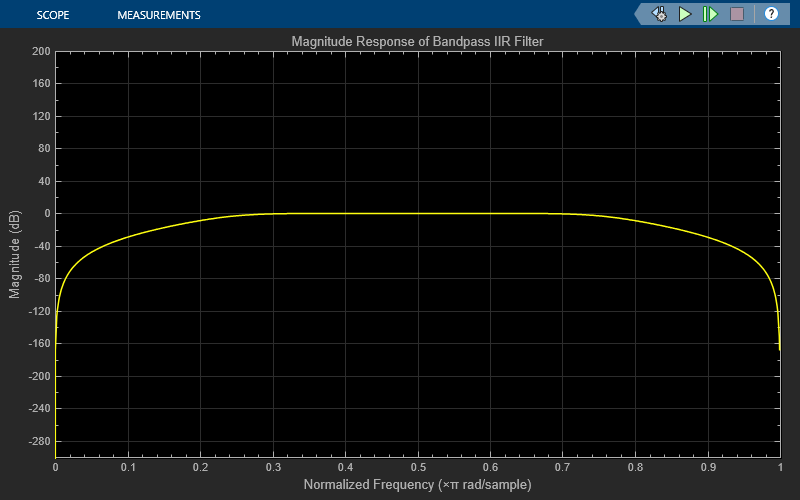
The Bandpass IIR Filter Design block designs a sixth-order bandpass IIR filter with the first and second 3-dB cutoff frequencies of 0.25  rad/sample and 0.75 rad/sample, respectively. The block generates coefficients as a cascade of second-order sections. Visualize the frequency response of the filter using the Filter Visualizer.
Run the model.
The Second-Order Section Filter block filters the noisy sinusoidal signal. Visualize the original sinusoidal signal and the filtered signal using the Spectrum Analyzer.


Tune Frequency Specifications of SOS Filter
During simulation, you can tune the frequency specifications of the SOS filter by tuning the frequency parameters in the Bandpass IIR Filter Design block. The frequency response of the SOS filter updates accordingly.
Change the second 3-dB cutoff frequency to 0.4 rad/sample in the Bandpass IIR Filter Design block. To change the parameter values more gradually during simulation, select the Smooth tuned filter parameters check box and specify a smoothing factor in the Bandpass IIR Filter Design block dialog box. The smoothing factor determines the speed at which the parameter values change until they match the desired new value. If you specify a smoothing factor of 0, the block does not smooth the parameter and immediately sets the parameter to the new value. As the smoothing factor approaches 1, the number of smoothing operations, and consequently, the number of filter redesigns increase. This example uses a smoothing factor is of 0.6.
When you change the second 3-dB cutoff frequency to 0.4 rad/sample, the second tone of the sinusoidal signal gets attenuated as it no longer falls in the passband region of the filter.


Filter a noisy sinusoidal signal using the Second-Order Section Filter block. Obtain the numerator and denominator coefficients of the SOS filter using the Bandstop IIR Filter Design block.
Tune the frequency specifications of the SOS filter during simulation.
Open and Run Model
Open the secondordersection_bandstopfilter model.
The input signal in the model is a sum of two sine waves with the frequencies of 200 Hz and 400 Hz. The sample rate is 1000 Hz and the number of samples in each frame is 1024. The Random Source block adds zero-mean white Gaussian noise with a variance of 1e-4 to the sum of the sine waves.
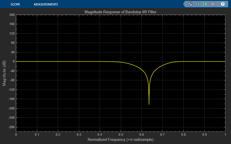
The Bandstop IIR Filter Design block designs a sixth-order bandstop IIR filter with the first and second 3-dB cutoff frequencies of 0.2  rad/sample and 0.75 rad/sample, respectively. The block generates coefficients as a cascade of second-order sections. Visualize the frequency response of the filter using Filter Visualizer.
Run the model.
The Second-Order Section Filter block filters the noisy sinusoidal signal. Visualize the original sinusoidal signal and the filtered signal using the Spectrum Analyzer. The first tone is attenuated as it falls in the stopband region of the filter while the second tone remains unaffected as it falls in the passband region of the filter.


Tune Frequency Specification of SOS Filter
During simulation, you can tune the frequency specifications of the SOS filter by tuning the frequency parameters in the Bandstop IIR Filter Design block. The frequency response of the SOS filter updates accordingly.
Change the first 3-dB cutoff frequency to 0.5 rad/sample in the Bandstop IIR Filter Design block. The first tone of the sinusoidal signal now falls in the passband region and is therefore unattenuated.

Ports
Input
Output
Parameters
Block Characteristics
Data Types |
|
Direct Feedthrough |
|
Multidimensional Signals |
|
Variable-Size Signals |
|
Zero-Crossing Detection |
|
More About
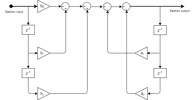
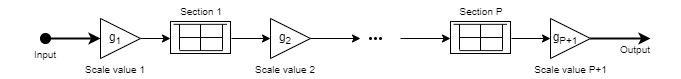
These diagrams show the filter structures supported by the second-order section filter.
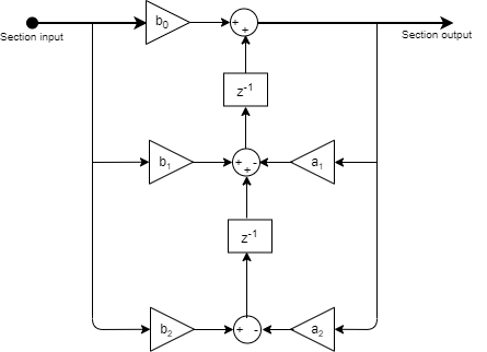
This is the structure of each section in the filter when you set the filter structure to
Direct form I.
This is the structure of the filter with P sections when you specify scale values [g1, g2, …, gP+1].
This is the structure of the filter when you do not specify scale values.

This is the structure of each section in the filter when you set the filter structure to
Direct form I transposed.

This is the structure of the filter with P sections when you specify scale values [g1, g2, …, gP+1].
This is the structure of the filter when you do not specify scale values.
This is the structure of each section in the filter when you set the filter structure to
Direct form II.

This is the structure of the filter with P sections when you specify scale values [g1, g2, …, gP+1].
This is the structure of the filter when you do not specify scale values.
This is the structure of each section in the filter when you set the filter structure to
Direct form II transposed.
This is the structure of the filter with P sections when you specify scale values [g1, g2, …, gP+1].
This is the structure of the filter when you do not specify scale values.
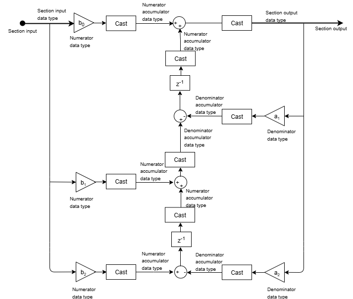
These diagrams show the data types used in the SOS filter when the input is fixed-point. For each structure the filter supports, the data types shown in the diagrams can be set through the respective fixed-point settings.
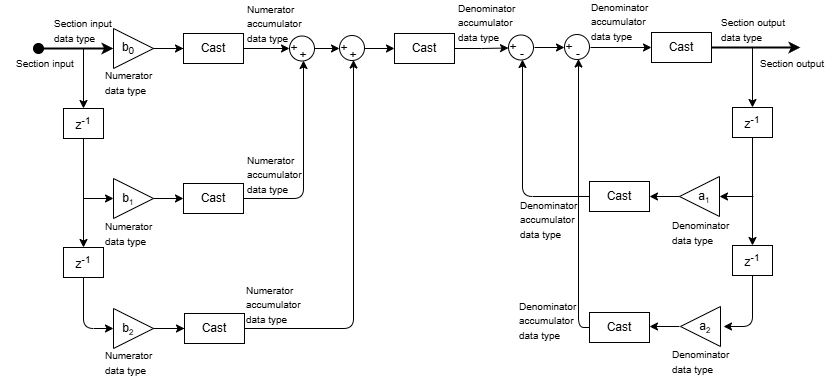
Here is the structure of each section when you set the filter structure to
Direct form I. This diagram shows the data types when you
input fixed-point signals. The gain operations
b0,
b1,
b2,
a1, and
a2 operate in full precision.
These diagrams show the fixed-point data types between filter sections.
When the data is not optimized:

When you specify scale values to 1:

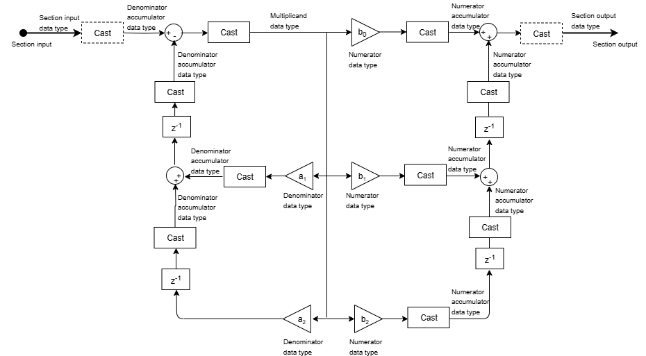
Here is the structure of each section when you set the filter structure to
Direct form I transposed. This diagram shows the data types
when you input fixed-point signals. The dashed casts are omitted when you set
HasScaleValues to false. The gain operations
b0,
b1,
b2,
a1, and
a2 operate in full precision.
These diagrams show the fixed-point data types between filter sections.
When the data is not optimized:

When you specify scale values to 1:

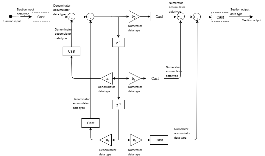
Here is the structure of each section when you set the filter structure to
Direct form II. This diagram shows the data types when you
input fixed-point signals. The dashed casts are omitted when you set
HasScaleValues to false. The gain operations
b0,
b1,
b2,
a1, and
a2 operate in full precision.
These diagrams show the fixed-point data types between filter sections.
When the data is not optimized:

When you set scale values to 1:

Here is the structure of each section when you set the filter structure to
Direct form II transposed. This diagram shows the data types
when you input fixed-point signals. The gain operations
b0,
b1,
b2,
a1, and
a2 operate in full precision. When you set
HasScaleValues to false, the data type at the
section output is automatically determined by the object algorithm and is not controlled
by the value of the SectionOutputDataType property.
These diagrams show the fixed-point data types between filter sections.
When the data is not optimized:

When you specify scale values to 1:
