dsphdl.FIRInterpolator
Description
The dsphdl.FIRInterpolator
System object™ implements a single-rate polyphase FIR interpolation filter that is optimized
for HDL code generation. The object provides a hardware-friendly interface with input and
output control signals. To provide a cycle-accurate simulation of the generated HDL code, the
object models architectural latency including pipeline registers and resource sharing.
The object accepts scalar or vector input and outputs a scalar or vector depending on the interpolation factor and the number of cycles between input samples. The object implements a polyphase decomposition with InterpolationFactor subfilters. The filter can implement a serial architecture if there is regular spacing between input samples.
The object provides two filter structures. The direct form systolic architecture provides a fully parallel implementation that makes efficient use of Intel® and Xilinx® DSP blocks. The direct form transposed architecture is a fully parallel implementation that is suitable for FPGA and ASIC applications. For a filter implementation that matches multipliers, pipeline registers, and pre-adders to the DSP configuration of your FPGA vendor, specify your target device when you generate HDL code.
For scalar input, all filter structures optimize hardware resources by sharing multipliers for symmetric or antisymmetric filters and by removing the multipliers for zero-valued coefficients such as in half-band filters and Hilbert transforms. When your input is a vector, the filter structure removes the multipliers for zero-valued coefficients but does not optimize for symmetric coefficients.
To filter and interpolate input data with an HDL-optimized algorithm::
Create the
dsphdl.FIRInterpolatorobject and set its properties.Call the object with arguments, as if it were a function.
To learn more about how System objects work, see What Are System Objects?
Note
You can also generate HDL code for this hardware-optimized algorithm, without creating a MATLAB® script, by using the DSP HDL IP Designer app. The app provides the same interface and configuration options as the System object.
Creation
Syntax
Description
firInterp = dsphdl.FIRInterpolatorfirInterp, which upsamples and filters the input signal with the
default settings.
firInterp = dsphdl.FIRInterpolator(
returns a System object
interp,num)firInterp with the InterpolationFactor property
set to interp and the Numerator property set to
num.
firInterp = dsphdl.FIRInterpolator(___,PropertyName=Value)
Properties
Usage
Syntax
Description
[
filters data using the coefficients dataOut,validOut,ready]
= firInterp(dataIn,validIn,coeff)coeff. Use this syntax when you
set the NumeratorSource property to 'Input port (Parallel
interface)'. For example:
firInterp = dsphdl.FIRDecimator(NumeratorSource='Input Port (Parallel interface)')
Numerator = myGetNumerator();  % calculate coefficients
for k=1:length(dataIn)
    [dataOut(x),validOut(x++)] = firInterp(dataIn(k),validIn(k),Numerator);
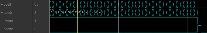
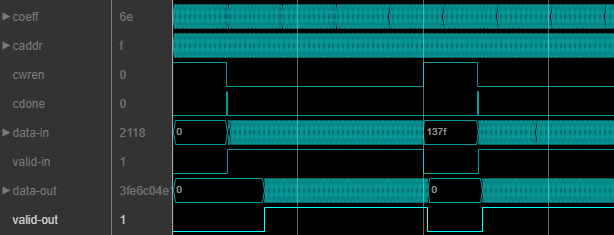
[
loads the coefficient value dataOut,validOut,ready]
= firInterp(dataIn,validIn,coeff,caddr,cwren,cdone)coeff to the caddr
memory location, when cwren is 1
(true). Set cdone to 1
(true) along with the last coefficient write, or after you finish
writing coefficients. The object ignores any input data provided when
cwren is 1 (true), but still
returns dataOut with validOut until it clears
the filter pipeline. Use this syntax when you set the NumeratorSource
property to 'Input port (Memory interface)'. For example:
firInterp = dsphdl.FIRInterpolator(NumeratorSource='Input Port (Memory interface)')
...
for k=1:length(Numerator)
    [dataOut(x),validOut(x++)] = firInterp(0,0,Numerator(k),k,true,(k==length(Numerator));
for k=1:length(dataIn)
[dataOut(x),validOut(x++)] = firInterp(dataIn(k),validIn(k),0,0,false,false);
[
filters data when dataOut,validOut]
= firInterp(dataIn,validIn,reset)reset is false. When
reset is true, the object resets the filter
registers. The object expects the reset argument only when you set
the ResetInputPort property to true.
For more reset considerations, see the Reset Signal section on the Hardware Control Signals page.
Input Arguments
Input data, specified as a real- or complex-valued scalar or vector. The vector size must be less than or equal to 64. When the input data type is an integer type or fixed-point type, the object uses fixed-point arithmetic for internal calculations.
The object has an output ready argument that indicates when
the object is ready for new input. Your design can react to the
ready argument before providing the next input sample, or you
can space your input data with enough cycles in between to process each sample. For
more information, see Backpressure Signal.
The software supports double and
single data types for simulation, but not for HDL code generation.
Data Types: fi | single | double | int8 | int16 | int32 | uint8 | uint16 | uint32
Complex Number Support: Yes
Control signal that indicates if the input data is valid. When
validIn is 1 (true), the
object captures the values from the dataIn argument. When
validIn is 0 (false), the
object ignores the values from the dataIn argument.
Data Types: logical
Since R2025a
Filter coefficients, specified as a vector of real or complex values. You can
change the input coefficients at any time. The size of the coefficient vector must
match the size of the sample coefficients specified in the
NumeratorPrototype property. The prototype specifies a sample
coefficient vector that is representative of the zero-value
locations of the expected input coefficients. The object uses the prototype to
optimize the filter
by
removing multipliers for zero-value coefficients.
If the input data is a fixed-point type, the
coeff values must also be of a fixed point type. If the input
data is a floating-point data type, the
coeff values must be of the same data type.
The software supports double and
single data types for simulation, but not for HDL code generation.
Dependencies
To enable this argument, set the NumeratorSource property
to 'Input port (Parallel interface)'.
Data Types: fi | single | double | int8 | int16 | int32 | uint8 | uint16 | uint32
Since R2023a
Filter coefficients, specified as a real or complex scalar value to write to
internal memory. To load a single coefficient value to internal memory, specify a
coeff value with a corresponding address in the
caddr argument and an enable signal in the
cwren argument. You can change the input coefficients at any
time.
While you write new coefficients into memory, the object ignores any input data,
but still returns dataOut with validOut
until it clears the filter pipeline. The object resumes accepting input one cycle
after cdone is set to 1
(true).
The
coefficient memory has the same number of addresses as the size of the
NumeratorPrototype property. The prototype specifies a sample
coefficient vector that is representative of the symmetry and zero-valued locations of
the expected input coefficients.
When you use
scalar input data, the object uses the prototype to optimize the filter by sharing
multipliers for symmetric or antisymmetric coefficients, and by removing multipliers
for zero-valued coefficients.
You must write the
entire set of coefficients to the memory, including symmetric or zero-value
coefficients. For example, if you set the NumeratorPrototype
property to a symmetric 14-tap filter, you must write 14 values to the memory
interface.
When you use frame-based input data, the object does not optimize the filter for
coefficient symmetry. The block still uses the NumeratorPrototype
property to remove multipliers for zero-valued coefficients. The coefficient memory
has the same number of locations as the size of the prototype.
If the input data is a fixed-point type, the
coeff values must also be of a fixed point type. If the input
data is a floating-point data type, the
coeff values must be of the same data type.
The software supports double and
single data types for simulation, but not for HDL code generation.
Dependencies
To enable this argument, set the NumeratorSource property
to 'Input port (Memory interface)'.
Data Types: fi | single | double | int8 | int16 | int32 | uint8 | uint16 | uint32
Since R2026a
Specify the filter coefficient address as a scalar integer value represented as an
unsigned fixed-point type with zero fractional bits. The object derives the size of
this integer value, and the size of the internal memory, from the number of unique
coefficients in the NumeratorPrototype property value.
The software supports double and
single data types for simulation, but not for HDL code generation.
Dependencies
To enable this argument, set the NumeratorSource property
to 'Input port (Memory interface)'.
Data Types: fi(0,N,0)
Since R2026a
Set this argument to 1 (true) to write the
value of the coeff argument into the caddr
location in internal memory.
The software supports double and
single data types for simulation, but not for HDL code generation.
Dependencies
To enable this argument, set the NumeratorSource property
to 'Input port (Memory interface)'.
Data Types: fi(0,N,0)
Since R2026a
Set this input to 1 (true) to indicate that
writing coefficients to memory is complete. You can set this input to
1 (true) along with the last coefficient
write, or on a later cycle with no active write.
The software supports double and
single data types for simulation, but not for HDL code generation.
Dependencies
To enable this argument, set the NumeratorSource property
to 'Input port (Memory interface)'.
Data Types: fi(0,N,0)
Control signal that clears internal states. When reset is
1 (true), the object stops the current
calculation and clears internal states. When the reset is
0 (false) and the input
valid is 1 (true), the
block captures data for processing.
For more reset considerations, see the Reset Signal section on the Hardware Control Signals page.
Dependencies
To enable this argument, set the ResetInputPort property to
true.
Data Types: logical
Output Arguments
Object Functions
To use an object function, specify the
System object as the first input argument. For
example, to release system resources of a System object named obj, use
this syntax:
release(obj)
Algorithms
This System object implements the algorithms described on the FIR Interpolator block reference page.