Monitor and Tune the Model Running on Renesas RA Microcontrollers
You can use Monitor and Tune (External Mode) action to tune parameters and monitor a Simulink® model running on your target hardware.
Monitor and Tune enables you to tune model parameters and evaluate the effects of different parameter values on model results in real-time. When you change parameter values in a model, the modified parameter values are communicated to the target hardware immediately. You can monitor the effects of different parameter values by viewing the output signals on Sink blocks or in the Simulation Data Inspector (SDI). This helps you find the optimal values for performance. This process is called parameter tuning.
Monitor and Tune accelerates parameter tuning. You do not have to rerun the model each time you change the parameters. You can also use Monitor and Tune to develop and validate your model using the actual data and hardware for which it is designed. This software-hardware interaction is not available by solely simulating a model.
The support package supports Monitor and Tune simulation over XCP on Serial when Renesas® Host Target is selected as hardware board:
The support package supports Monitor and Tune simulation over XCP on Serial when
Renesas RA6 Based Board is selected as the hardware board:
| Communication Interface | Description |
|---|---|
XCP on Serial | In Universal Measurement and Calibration Protocol (XCP)-based External mode simulation over Serial, you can use:
|
These sections explain:
Prepare a Simulink Model for External Mode
This section explains how to prepare a Simulink model to run in External mode.
Configure the Model Configuration Parameters to set the Hardware Board as one of the supported Renesas hardware boards, as explained in Model Configuration Parameters.
In the Model Configuration Parameters dialog box, under Hardware board settings > Target Hardware Resources, select External Mode tab.
When
Renesas RA6 Basedis selected as hardware board, Communication interface isXCP on Serial.
Ensure that you select the Verbose check box to view the external mode execution progress and updates in the Diagnostic Viewer or in the Command Window.
Select the Set logging buffer size automatically parameter to automatically set the number of bytes to preallocate for the buffer in the hardware during simulation. By default, the Set logging buffer size automatically parameter is selected. If you clear this parameter, Logging buffer size (in bytes) parameter becomes available, where you can manually specify the memory buffer size for XCP-based External mode simulation.
Click Apply and then OK to close the Model Configuration Parameters dialog box.
Running the Simulink Model for Monitor and Tune
Connect the Renesas RA Microcontroller hardware to your host computer.
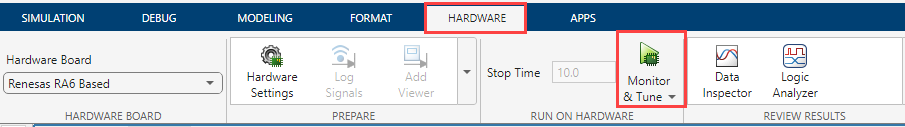
Open the Simulink model and go to Hardware tab.
Set a value for the Simulation stop time parameter. The default value is
10.0seconds. To run the model for an indefinite period, enterinf.On the Hardware tab click Monitor & Tune to run the model on external mode.
Simulink automatically:
Runs the model on the target hardware.
Runs the model on the host computer for Monitor and Tune operation.
Creates a real-time connection between the model on target hardware and the model on the host computer.
Signal Monitoring and Parameter Tuning of Simulink Model
This section explains how to run:
XCP-Based External Mode Simulation over Serial
Before you begin, complete the Prepare a Simulink Model for External Mode section.
In the Simulink model, identify the signals to be logged for monitoring during simulation. Select the identified signal, open its context menu, and click the icon corresponding to Enable Data Logging.
For instructions on logging the signal using other methods, refer to Mark Signals for Logging. Simulink displays a logged signal indicator
 for each logged signal.
(Optional) Place one or more Sink blocks in the model, and then mark the signals connected to them also for logging. For example, connect Display or Scope blocks and mark the signals connected to them for logging.
To start the simulation, on the Hardware tab click Monitor & Tune.
For instructions on logging the signal, see Mark Signals for Logging.
After several minutes, Simulink starts running the model on the hardware.
During simulation, when new simulation data becomes available in SDI, the Simulation Data Inspector button
 appears highlighted.
View the simulation output in Sink blocks or in SDI.
Note
For XCP- Based External Mode over Serial, it is recommended to use Signal Data Inspector (SDI) to view and log signals.
Sink blocks – To view the simulation output, double-click the Sink blocks in the model.
SDI – To view the new simulation data, perform these steps:
Click the Simulation Data Inspector button.
A new simulation run appears in the Inspect pane. The Inspect pane lists all logged signals in rows, organized by simulation run. You can expand or collapse any of the runs to view the signals in a run. For more information on signal grouping, see Signal Groups.
We recommend you use SDI rather than using Sink blocks for the following reasons:
Streaming data to SDI does not store data in memory, making more efficient use of the memory available on the hardware. Sink blocks such as Scope stores data in buffers before sending the data to the host.
Using SDI, you can stream signals from top models and reference models simultaneously. Scope blocks can only log signals from a top-level model.
Change the parameter values in the model. Observe the corresponding changes in the simulation output.
Find the optimal parameter values by adjusting and observing the results in the Sink blocks.
After you are satisfied with the results, stop the Monitor and Tune action, and save the model.
Stop Monitor and Tune
To stop the model that is running in Monitor and Tune, open the
Hardware tab and click the Stop button ![]() .
.
If the Simulation stop time parameter is set to a specific number of seconds, Monitor and Tune stops when that time elapses.