ctrectcorners
Corner measurements of constant turn-rate rectangular target
Description
Examples
Define sensor reference frame by specifying the sensorParameters input.
sensorPosition = [-5;10;0];
sensorOrientation = rotmat(quaternion([30 0 0],'eulerd','ZYX','frame'),'frame');
sensorParams = struct('Frame','Rectangular', ...
    'OriginPosition',sensorPosition,...
    'Orientation',sensorOrientation);
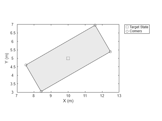
Define the constant turn-rate state for the rectangle target.
state = [10;5;1.6;30;0.5;4.7;1.8];
Compute corner positions in sensor reference frame.
corners = ctrectcorners(state,sensorParams);
Set up visualization environment using theaterPlot.
% Create a theater plot.
tp = theaterPlot;
% Plot the state using a track plotter.
statePlotter = trackPlotter(tp,'DisplayName','Target State');
% Plot the corners using a detection plotter.
cornerPlotter = detectionPlotter(tp,'DisplayName','Corners');
Compute inputs and plot.
targetPos = [state(1) state(2) 0];
targetOrientation = rotmat(quaternion([state(4) 0 0],'eulerd','ZYX','frame'),'frame');
targetDims = struct('Length',state(6),...
    'Width',state(7),...
    'Height',5,...
    'OriginOffset',[0 0 0]);

cornerPosGlobal = sensorOrientation*corners(:,:) + sensorPosition;
statePlotter.plotTrack(targetPos,targetDims,targetOrientation);
cornerPlotter.plotDetection(cornerPosGlobal');

Input Arguments
Current rectangular target states, specified as a 7-by-N real-valued matrix, where N is the number of states. The seven dimensional rectangular state is defined as [x; y; s; θ; ω; L; W]. The meaning of these variables and their units are:
| Variable | Meaning | Unit |
| x | Position of the rectangle center in x direction | m |
| y | Position of the rectangle center in y direction | m |
| s | Speed in the heading direction | m/s |
| θ | Orientation angle of the rectangle with respect to x direction | degree |
| ω | Turn-rate | degree/s |
| L | Length of the rectangle | m |
| W | Width of the rectangle | m |
Example: [1;2;2;30;1;4.7;1.8]
Data Types: single | double
Parameters for the sensor transform function, returned as a structure or an array of structures. If you only need to transform the state once, specify it as a structure. If you need to transform the state n times, specify it as an n-by-1 array of structures. For example, to transform a state from the scenario frame to the sensor frame, you usually need to first transform the state from the scenario rectangular frame to the platform rectangular frame, and then transform the state from the platform rectangular frame to the sensor spherical frame.
The fields of the structure are:
| Field | Description |
Frame | Child coordinate frame type, specified as
|
OriginPosition | Child frame origin position expressed in the parent frame, specified as a 3-by-1 vector. |
OriginVelocity | Child frame origin velocity expressed in the parent frame, specified as a 3-by-1 vector. |
Orientation | Relative orientation between frames, specified as a 3-by-3 rotation
matrix. If the |
IsParentToChild | Flag to indicate the direction of rotation between parent and child
frame, specified as |
HasAzimuth | Indicates whether outputs contain azimuth components, specified as
|
HasElevation | Indicates whether outputs contain elevation components, specified as
|
HasRange | Indicates whether outputs contain range components, specified as
|
HasVelocity | Indicates whether outputs contain velocity components, specified as
|
Note that here the scenario frame is the parent frame of the platform frame, and the platform frame is the parent frame of the sensor frame.
When frame is 'Rectangular',
HasVelocity determines if the measurement is returned in the form
of [x; y; z;
vx;
vy;
vz] or
[x; y; z].
When frame is 'spherical', the returned
measurements are in the order of [azimuth, elevation, range, range-rate]. The elements
of the returned measurements are determined by:
HasAzimuth— Determines if output contains azimuth measurement.HasElevation— Determines if output contains elevation measurement.HasRange— Determines if output contains range measurement.HasVelocity— Determines if output contains range-rate measurement on the condition thatHasRangeis'true'. IfHasRangeis'false', the returned measurement does not contain range-rate (even thoughHasVelocityis'true').
Data Types: struct
Output Arguments
States of corners, returned as a real-valued
M-by-N-by-4 array. Each page (an
M-by-N matrix) of the array corresponds to one
corner for all the states given in the states input. N is the number
of states. M is the dimension of output specified by the
sensorParameters input. If unspecified, the default value of
M is three, which corresponds to 3-D Cartesian position
coordinates.
Extended Capabilities
C/C++ Code Generation
Generate C and C++ code using MATLAB® Coder™.
Version History
Introduced in R2018b
See Also
gmphd | trackerPHD | ctrect | ctrectmeas | ctrectmeasjac | ctrectjac | initctrectgmphd
MATLAB Command
You clicked a link that corresponds to this MATLAB command:
Run the command by entering it in the MATLAB Command Window. Web browsers do not support MATLAB commands.
选择网站
选择网站以获取翻译的可用内容,以及查看当地活动和优惠。根据您的位置,我们建议您选择:。
您也可以从以下列表中选择网站:
如何获得最佳网站性能
选择中国网站(中文或英文)以获得最佳网站性能。其他 MathWorks 国家/地区网站并未针对您所在位置的访问进行优化。
美洲
- América Latina (Español)
- Canada (English)
- United States (English)
欧洲
- Belgium (English)
- Denmark (English)
- Deutschland (Deutsch)
- España (Español)
- Finland (English)
- France (Français)
- Ireland (English)
- Italia (Italiano)
- Luxembourg (English)
- Netherlands (English)
- Norway (English)
- Österreich (Deutsch)
- Portugal (English)
- Sweden (English)
- Switzerland
- United Kingdom (English)