Customize Clock Bundle Names in Generated Code
When you generate code from a multirate model, HDL Coder™ names the clock bundle names using the signal name, followed by the sample rate. HDL Coder orders signal names by rate. HDL Coder lists base-rate signals first, followed by slower subrate signals.
You can customize the names of these signals by using the Clock input port, Reset input port, and Clock enable input port model configuration parameters.
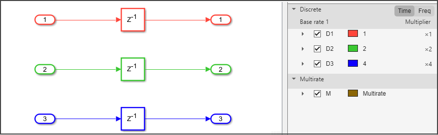
For example, this figure shows a multirate model that has three sample rates.
Suppose that you generate HDL code from the model. This code shows the default naming convention for clock bundle signals.
ENTITY Subsystem IS
PORT( clk : IN std_logic;
clk_1_2 : IN std_logic;
clk_1_4 : IN std_logic;
reset : IN std_logic;
reset_1_2 : IN std_logic;
reset_1_4 : IN std_logic;
clk_enable : IN std_logic;
clk_enable_2 : IN std_logic;
clk_enable_4 : IN std_logic;
In1 : IN std_logic_vector(15 DOWNTO 0); -- int16
In2 : IN std_logic_vector(15 DOWNTO 0); -- int16
In3 : IN std_logic_vector(15 DOWNTO 0); -- int16
Out1 : OUT std_logic_vector(15 DOWNTO 0); -- int16
Out2 : OUT std_logic_vector(15 DOWNTO 0); -- int16
Out3 : OUT std_logic_vector(15 DOWNTO 0) -- int16
);
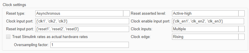
END Subsystem;To customize names for the clock, reset, and clock enable signals, open the Configuration Parameters dialog box. In the left pane, click HDL Code Generation > Global Settings.
Alternatively, you can use the hdlset_param function to set
the model configuration parameter
programmatically.
hdlset_param(ModelName,"ClockInputPort",{"clk1","clk2","clk3"})
hdlset_param(ModelName,"ResetInputPort",{"reset1","reset2","reset3"})
hdlset_param(ModelName,"ClockEnableInputPort",{"clk_en1","clk_en2","clk_en3"})
When specifying custom signal names:
Use cell arrays to specify multiple signal names. For example,
{"clk1","clk2","clk3"}.Ensure each signal name is unique.
The number of signal names must match the number of sample rates in a model.
This code shows the generated HDL code for a multirate model that uses custom naming for clock, reset, and clock enable signals. HDL Coder maps the signal names in the order from the fastest rate, which is the base rate of the model, to the slowest rate.
ENTITY Subsystem IS
  PORT( clk1                              :   IN    std_logic;
        clk2                              :   IN    std_logic;
        clk3                              :   IN    std_logic;
        reset1                            :   IN    std_logic;
        reset2                            :   IN    std_logic;
        reset3                            :   IN    std_logic;
        clk_en1                           :   IN    std_logic;
        clk_en2                           :   IN    std_logic;
        clk_en3                           :   IN    std_logic;
        In1                               :   IN    std_logic_vector(15 DOWNTO 0);  -- int16
        In2                               :   IN    std_logic_vector(15 DOWNTO 0);  -- int16
        In3                               :   IN    std_logic_vector(15 DOWNTO 0);  -- int16
        Out1                              :   OUT   std_logic_vector(15 DOWNTO 0);  -- int16
        Out2                              :   OUT   std_logic_vector(15 DOWNTO 0);  -- int16
        Out3                              :   OUT   std_logic_vector(15 DOWNTO 0)  -- int16
        );
END Subsystem;
See Also
Clock inputs | Clock input port | Reset input port | Clock enable input port