Generate IP Core from I2C Controller Model Built Using Stateflow
This example illustrates how to model an I2C controller using an I2C Master controller modeled using Stateflow® blocks for configuring the audio codec chip.
In this example, you:
Model the I2C Master Controller using Stateflow blocks in Simulink®
Model the I2C Controller using the I2C Master Controller block for configuring the Audio Codec Chip
Use the blackbox subsystem and bidirectional port features to handle tri-state logic in I2C IP core
Use the IP Core Generation workflow to generate an IP core for the I2C Controller
1. Overview of I2C Protocol
I2C bus, also called Inter-IC bus, is a simple, multi-master, multi-slave, bidirectional two-wire bus, that consists of serial data (SDA) and serial clock (SCL) lines. Each device connected to the bus is software addressable by a unique 7-bit or 10-bit address, and maintains a simple master-slave relationship. Serial, 8-bit oriented, bi-directional data transfers can be made at up to 100 kbit/s in the Standard mode, up to 400 kbit/s in the Fast-mode,or up to 3.4 Mbit/s in the High-speed mode. I2C bus has two nodes: master node and slave node. The master node generates clock and initiates communication with the slave. The slave node which is addressed by the master receives clock and responds to the master during acknowledgment. There are four modes of operation which are master transmit, master receive, slave transmit and slave receive. The master starts the communication by sending start bit followed by 7 or 10 bit address of the slave followed by read(1) or write(0) bit. If the slave corresponding to that address is present, then it responds with ACK bit. The master continues communication in transmit or receive mode based on the read or write bit. Similarly, the slave continues its operation based on the read or write instruction from the master. The figure below shows the timing diagram of I2C protocol.

2. Modeling Generalized I2C Master Controller in Simulink Using Stateflow Blocks
Configuring multiple peripherals in the design can be a cumbersome and tedious process. Instead, create a generic I2C Master Controller that you can directly use to configure the audio codec chips. The figure below shows the architecture of the Generalized I2C Master Controller which is implemented using Stateflow blocks in Simulink.

The above part shows the I2C Master Controller block. To configure the peripheral, you must provide device-specific configuration to the I2C Master Controller block. The block diagram to configure the audio codec chip using I2C Master Controller is as shown below.

The below model shows the I2C Master Controller which is modeled in Simulink using Stateflow blocks.
modelname = 'hdlcoder_I2C_master_controller';
open_system(modelname);
open_system('hdlcoder_I2C_master_controller/I2C_MasterController');
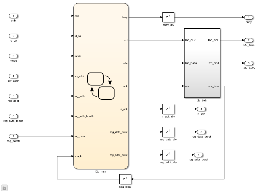
The I2C Master Controller only supports I2C write and doesn't support I2C readback currently. I2C Master Controller consists of two parts, I2C Master Controller chart and tristate buffer blackbox. I2C Master Controller chart provides serial data, SDA and serial clock, SCL to slave device through the tristate buffer blackbox. Tristate buffer blackbox uses the handwritten VHDL code and used for the bidirectional functionality of the SDA port. Tristate buffer blackbox is added in the model as Simulink doesn't support bidirectional port modeling.
To create a blackbox use the following steps.
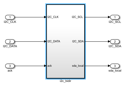
1. Make a subsystem which contains input and output ports of the HDL source code which you want to import for the blackbox creation. The I2C tristate buffer blackbox is as shown below.
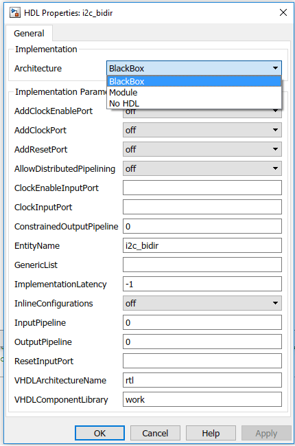
2. To specify your subsystem as a black box interface, right click on the subsystem and select HDL Code > HDL Block Properties and set the Architecture to Blackbox as shown in the following figure.
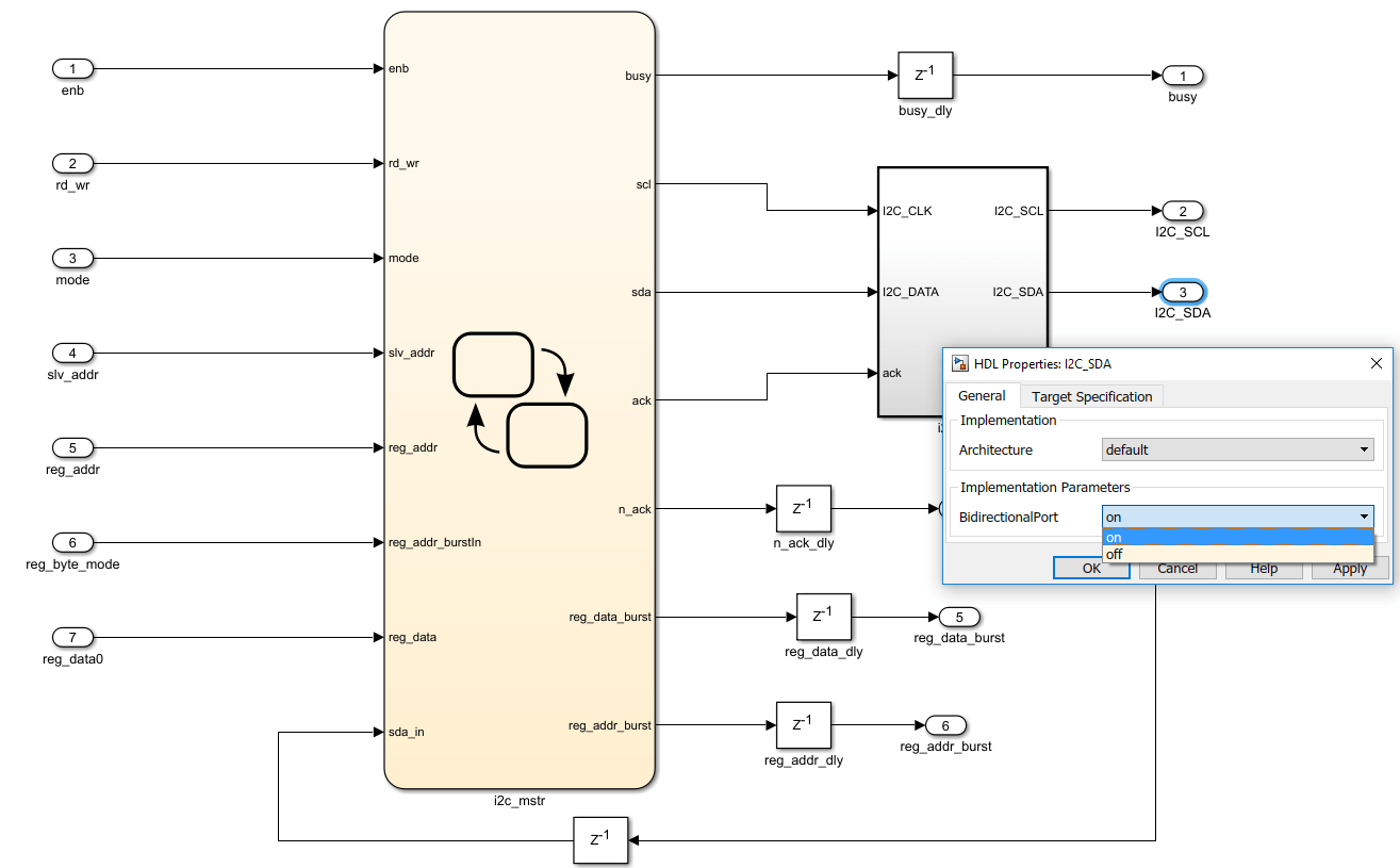
3. The data port I2C_SDA of I2C Master Controller is bidirectional. To set the port as bidirectional, right click on the I2C_SDA port and click on HDL block properties and set the BidirectionalPort on as shown below.
4. During simulation, the actual content inside of the blackbox subsystem will be used for simulation.
During code generation, HDL Coder™ will not generate the code under the blackbox subsystem. Instead, the code generator integrates your hand-written HDL code into the IP core. Inputs to the I2C Master Controller block can be provided by adding a device specific configuration chart at the input. This chart contains details about the registers that need to be configured for your slave device. More about device configuration is covered in the section of Zedboard™, Zybo board and Arrow® SoC Development Kit Audio Codec configuration using I2C Master Controller.
2.1 I/O Description of I2C Master Controller Block
The following figure gives the details about input and output ports of the I2C Master Controller block.
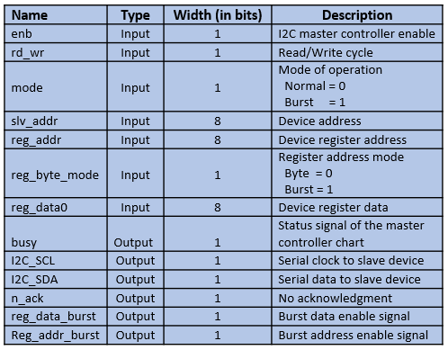
2.2 Description of I2C Master Controller Stateflow Chart
I2C Master Controller chart is made in such a way that in all the states required clock (SCL) is generated and data is provided as per the I2C protocol through serial data (SDA) port. Following states shows the generation of the clock and start bit.
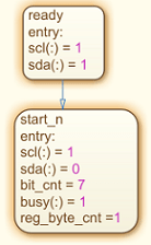
The following states are used to send 7-bit address of the slave device.
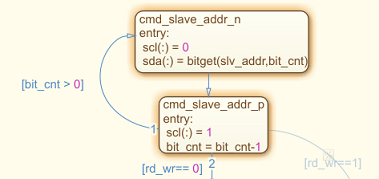
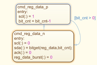
The function bitget is used to send bits serially to SDA port. It allows user to get bit value at specified position of the integer mentioned in its argument list. The transition from one state to other state depends on execution order specified for the transition conditions. As shown in the above figure the transition from cmd_slave_addr_p to the cmd_slave_addr_n state occurs based on the transition condition(bit_cnt > 0). The value of bit_cnt keeps decrementing until the transition condition satisfies. The value of bit_cnt is initialized to '7' and its value decrements till it becomes '1' which is used to send 7-bit address of slave device on SDA port. For HDL code generation, supported data types must be used. Colon(:) operator as shown in the states which is a typecasting operator used in cmd_slave_addr_n state(scl(:)= 0) converts a value of type 'double' to a type 'logical' (SCL is the logical datatype in the states shown). The states shown below are used to send register address to the slave device.
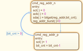
The states shown below are used to send register data to the slave device.
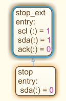
Following states shows the stop bit generation.
3. Configuring Audio Codec ADAU1761 on Zedboard Using I2C Master Controller Library Block
This section shows how to:
Model audio codec ADAU1761 device configuration chart using Stateflow blocks in Simulink.
Use I2C Master controller library block to configure audio codec ADAU1761.
Perform simulation of created model.
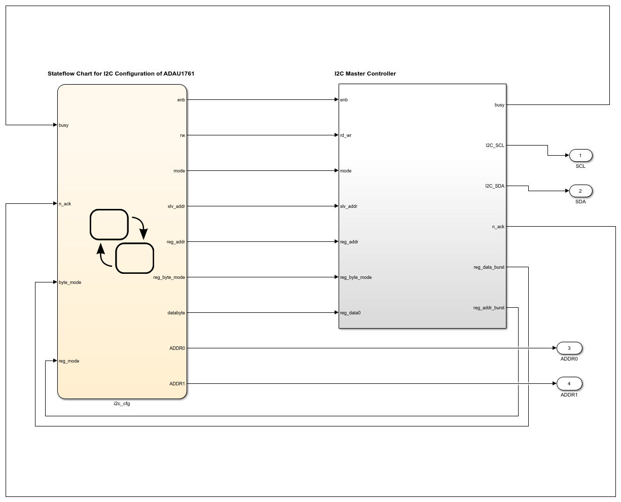
As mentioned earlier to configure the audio codec ADAU1761 on Zedboard, device configuration chart for ADAU1761 need to be created. This chart should be connected to the I2C Master controller library block created earlier.
Note: You have to create device configuration chart for your own device. This example is to show how the I2C Master Controller library block can be used to configure audio codec devices. The device configuration chart used for ADAU1761 is specific to this device and can't be used to configure other devices.
The configuration model created for ADAU1761 is as shown below.
modelname = 'hdlcoder_I2C_adau1761';
open_system(modelname);
3.1 Simulating Audio Codec ADAU1761 Configuration Model
For Audio codec chip ADAU1761, 20 registers need to be configured. Few of them have to be written by I2C Master Controller in burst mode and few in byte mode. The first register is written in byte mode, second in burst mode of length 6-bytes. Remaining 18 registers are written in byte mode.
Simulation waveform for configuration of audio codec ADAU1761 is as shown below.
Byte mode transfer between I2C Master Controller and audio codec chip ADAU1761 is shown in the following figure.
Below simulation shows sending of start bit, followed by 7-bit address of the slave device(0x3B), followed by write(0) bit, followed by 16-bit register address(0x4000), followed by 8-bit register data(0x0E) and acknowledgments from the slave device.

3.2 IP Core Generation Workflow
To generate the audio codec ADAU1761 configuration HDL IP core, follow the steps given below.
1. Set up the Xilinx® Vivado® synthesis tool path by using the hdlsetuptoolpath command. Use your own Vivado installation path when you run the command.
hdlsetuptoolpath('ToolName', 'Xilinx Vivado', 'ToolPath', vivadopath);
2. In the ADAU1761 configuration model, select I2C_IP subsystem and by right clicking open HDL workflow advisor. In Task 1.1, Select IP Core Generation for Target workflow, Generic Xilinx Platform for Target platform and Xilinx Vivado for Synthesis Tool. Also select family, device, package and speed.
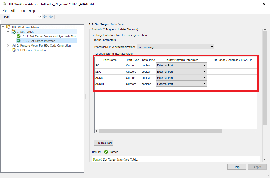
3. In Task 1.2, set the Target Platform Interfaces to "External Port" for all the ports.
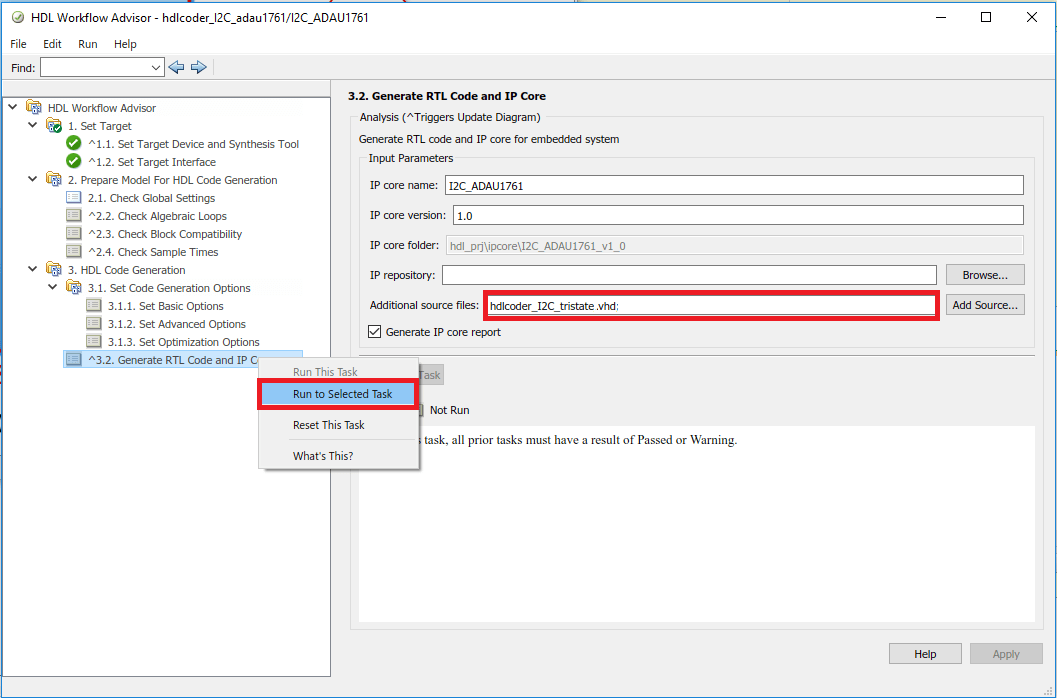
4. In Task 3.2, add the tristate buffer VHDL file in the additional source files. Then right click on Generate RTL code and IP Core and click on Run to Selected Task.
I2C IP Core for configuration of ADAU1761 will be generated. Below figure shows the IP Core generation report.
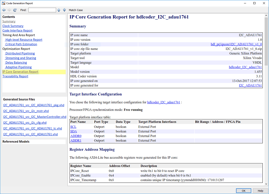
Generated IP core can be used in user reference designs. For creating the reference design, refer to Build Custom Reference Design to Interface with Peripheral Chip.
4. Configuring Audio Codec SSM2603 on Zybo Board Using I2C Master Controller Library Block
This section shows how to:
Model audio codec SSM2603 device configuration chart using Stateflow blocks in Simulink.
Use I2C Master controller library block to configure audio codec SSM2603.
Perform simulation of created model.
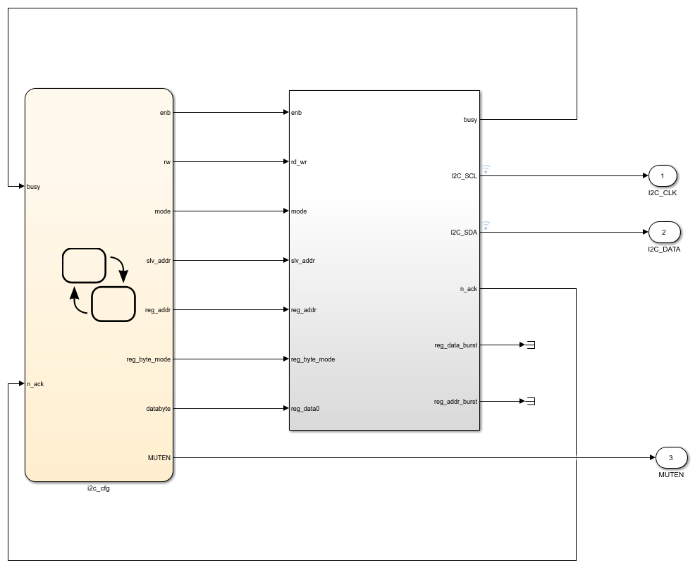
To configure the audio codec SSM2603 on Zybo board, device configuration chart for SSM2603 need to be created. This chart should be connected to the I2C Master controller library block created earlier.
Note: The device configuration chart used for SSM2603 is specific to this device and can't be used to configure other devices.
The configuration model created for SSM2603 is as shown below.
modelname = 'hdlcoder_I2C_ssm2603';
open_system(modelname);
4.1 Simulating Audio Codec SSM2603 Configuration Model
For Audio codec chip SSM2603, 11 registers need to be configured. All the to be written in byte mode.
Simulation waveform for configuration of audio codec SSM2603 is as shown below.
Below simulation shows sending of start bit, followed by 7-bit address of the slave device(0x1A), followed by write(0) bit, followed by 8-bit register address(0x0C), followed by 8-bit register data(0x10) and acknowledgments from the slave device.

4.2 IP Core Generation Workflow
IP Core generation steps for SSM2603 configuration model are same as the steps mentioned above in section 3.2, IP Core generation workflow. Generated IP core can be used in user reference designs. For creating the reference design, refer to Authoring a Reference Design for Audio System on a ZYBO Board.
5 Configuring Audio Codec SSM2603 on Arrow SoC Development Kit Using I2C Master Controller Library Block
This section shows how to:
Model audio codec SSM2603 device configuration chart using Stateflow blocks in Simulink.
Use I2C Master controller library block to configure audio codec SSM2603.
Perform simulation of created model.
To configure the audio codec SSM2603 on Arrow SoC Development Kit, device configuration chart for SSM2603 need to be created. This chart should be connected to the I2C Master controller library block created earlier.
Note: The device configuration chart used for SSM2603 is specific to this device and can't be used to configure other devices.
The configuration model for SSM2603 on Arrow SoC Development Kit is same as configuration model for SSM2603 on Zybo board. Refer to section 4 of this article for SSM2603 configuration model.
5.1 Simulating Audio Codec SSM2603 Configuration Model
The audio codec chip SSM2603 configuration on Arrow SoC Development Kit is same as audio codec chip SSM2603 configuration on Zybo board. Refer to section 4.1 of this article for simulation.
5.2 IP Core Generation Workflow
To generate the audio codec SSM2603 configuration HDL IP core, follow the steps given below.
1. Set up the Intel® Quartus® tool path using the hdlsetuptoolpath command. Use your own Quartus installation path when you run the command
hdlsetuptoolpath('ToolName', 'Altera Quartus II', 'ToolPath', quartuspath);
2. In the SSM2603 configuration model, select I2C_SSM2603 subsystem and by right clicking open HDL workflow advisor. In Task 1.1, Select IP Core Generation for Target workflow, Generic Altera Platform for Target platform and Altera QUARTUS II for Synthesis Tool. Also select family, device, package and speed.
3. In Task 1.2, set the Target Platform Interfaces to "External Port" for all the ports.
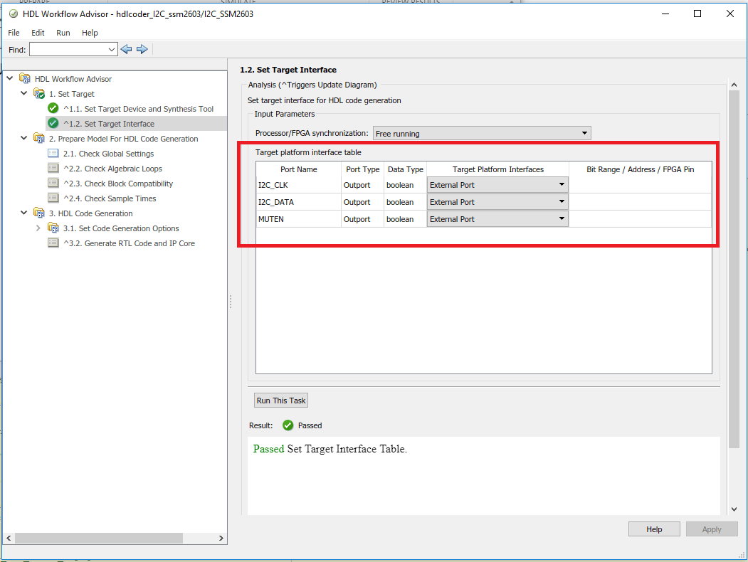
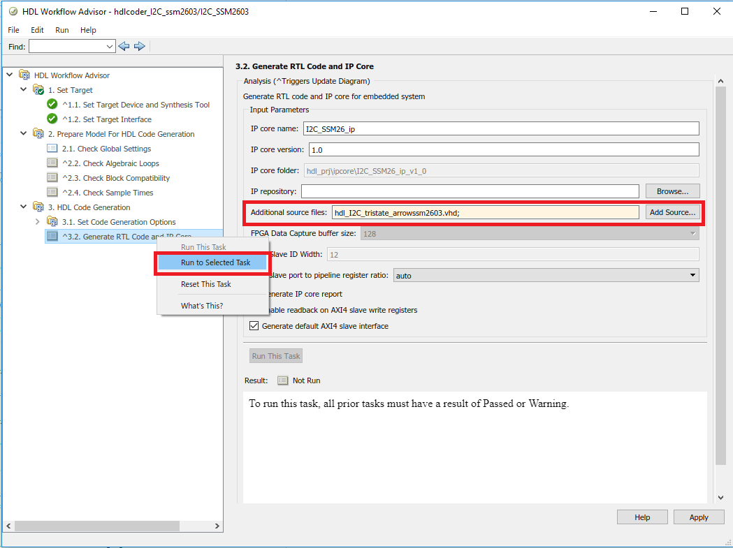
4. In Task 3.2, add the tristate buffer Verilog file in the additional source files. Then right click on Generate RTL code and IP Core and click on Run to Selected Task.
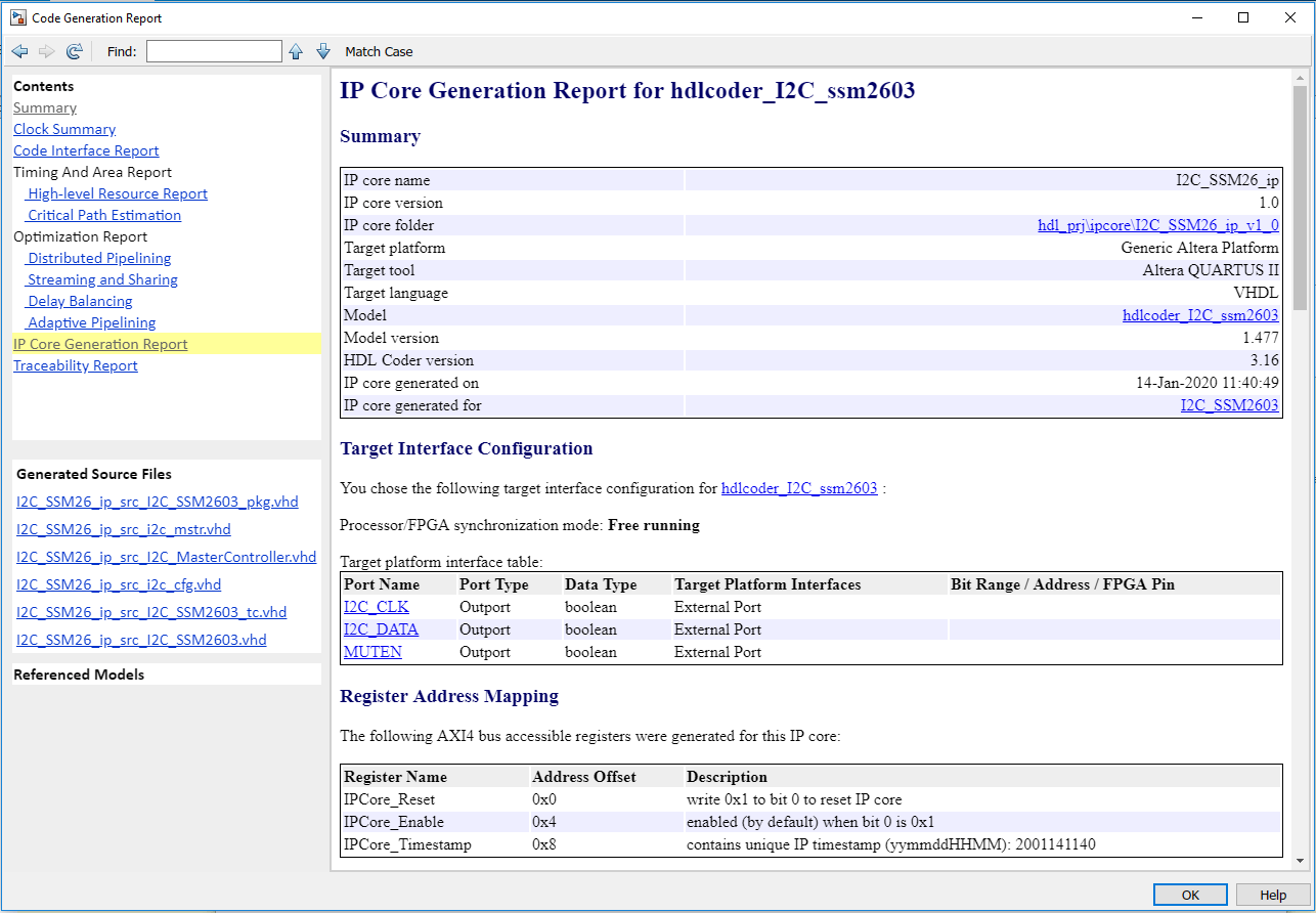
I2C IP Core for configuration of SSM2603 will be generated. Below figure shows the IP Core generation report.
Generated IP core can be used in user reference designs. For creating the reference design, refer to Author Audio System Reference Design for Basic Intel Evaluation Board.