HDL Code Generation for a System with Multiple Independent Clock Domains
You can generate HDL code for a system with multiple independent clock domains using HDL Coder™ by:
Using different rates: You can use different rates in Simulink® to represent each clock domain. The generated clock names are based on their Simulink rates, but they can be connected arbitrarily when instantiating the resulting HDL code.
Using Trigger Signals as Clocks: You can use triggered subsystems and resettable subsystems to explicitly represent clocks and resets as signals in Simulink.
This example demonstrates how to use these two methods to generate HDL code for a system with multiple clock domains that do not transfer data between them using HDL Coder. The system consists of two counters operating at different clock rates.
Using Different Rates in Simulink
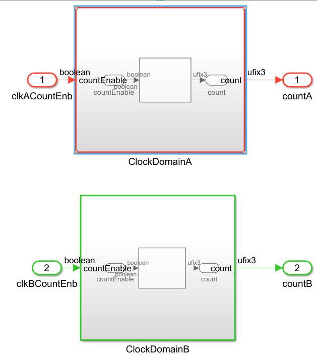
You can use different rates in Simulink to represent each clock domain. In this example, the sample times of the counters are set to 1 and 2, respectively.
load_system('hdlcoderMultipleRatesDemo');
open_system('hdlcoderMultipleRatesDemo/DUT');
set_param('hdlcoderMultipleRatesDemo', 'SimulationCommand', 'update');

To generate multiple synchronous clocks for this design, the ClockInputs property must be set to multiple. Either change the ClockInputs property at the command line using makehdl or change the Clock Inputs Setting to Multiple on the HDL Code Generation > Global Settings tab of the Configuration Parameters dialog box. If you do not want to generate clock enable logic, set MinimizeClockEnables to on.
makehdl('hdlcoderMultipleRatesDemo/DUT', 'ClockInputs', 'multiple', 'MinimizeClockEnables', 'on');
### Working on the model hdlcoderMultipleRatesDemo
### Generating HDL for hdlcoderMultipleRatesDemo/DUT
### Using the config set for model hdlcoderMultipleRatesDemo for HDL code generation parameters.
### Running HDL checks on the model 'hdlcoderMultipleRatesDemo'.
### Begin compilation of the model 'hdlcoderMultipleRatesDemo'...
### Begin compilation of the model 'hdlcoderMultipleRatesDemo'...
### Working on the model 'hdlcoderMultipleRatesDemo'...
### Working on... GenerateModel
### Begin model generation 'gm_hdlcoderMultipleRatesDemo'...
### Copying DUT to the generated model....
### Model generation complete.
### Generated model saved at hdlsrc/hdlcoderMultipleRatesDemo/gm_hdlcoderMultipleRatesDemo.slx
### Begin VHDL Code Generation for 'hdlcoderMultipleRatesDemo'.
### Working on hdlcoderMultipleRatesDemo/DUT/ClockDomainA as hdlsrc/hdlcoderMultipleRatesDemo/ClockDomainA.vhd.
### Working on hdlcoderMultipleRatesDemo/DUT/ClockDomainB as hdlsrc/hdlcoderMultipleRatesDemo/ClockDomainB.vhd.
### Working on hdlcoderMultipleRatesDemo/DUT as hdlsrc/hdlcoderMultipleRatesDemo/DUT.vhd.
### Code Generation for 'hdlcoderMultipleRatesDemo' completed.
### Generating HTML files for code generation report at index.html
### Creating HDL Code Generation Check Report DUT_report.html
### HDL check for 'hdlcoderMultipleRatesDemo' complete with 0 errors, 0 warnings, and 0 messages.
### HDL code generation complete.
In synchronous multiple clock mode, the generated code includes clock ports as primary inputs to the DUT, with each clock port corresponding to a distinct rate in the model. HDL Coder provides separate clock, reset, and clock enable inputs for each rate, as shown in this code snippet.
ENTITY DUT IS
  PORT( clk                               :   IN    std_logic;
        clk_1_2                           :   IN    std_logic;
        reset                             :   IN    std_logic;
        reset_1_2                         :   IN    std_logic;
        clkACountEnb                      :   IN    std_logic;
        clkBCountEnb                      :   IN    std_logic;
        countA                            :   OUT   std_logic_vector(2 DOWNTO 0);  -- ufix3
        countB                            :   OUT   std_logic_vector(2 DOWNTO 0)  -- ufix3
        );
END DUT;
...
BEGIN
  u_ClockDomainA : ClockDomainA
    PORT MAP( clk => clk,
              reset => reset,
              countEnable => clkACountEnb,
              count => ClockDomainA_out1  -- ufix3
              );

  u_ClockDomainB : ClockDomainB
    PORT MAP( clk_1_2 => clk_1_2,
              reset_1_2 => reset_1_2,
              countEnable => clkBCountEnb,
              count => ClockDomainB_out1  -- ufix3
              );
Limitations
Clock names cannot be independently customized. The name for the clock input ports in generated HDL code will all be prefixed with the string specified for the Clock input port.
If there is data transfer between clock domains refer to Using Multiple Clocks in HDL Coder.
Using Trigger Signal as Clock
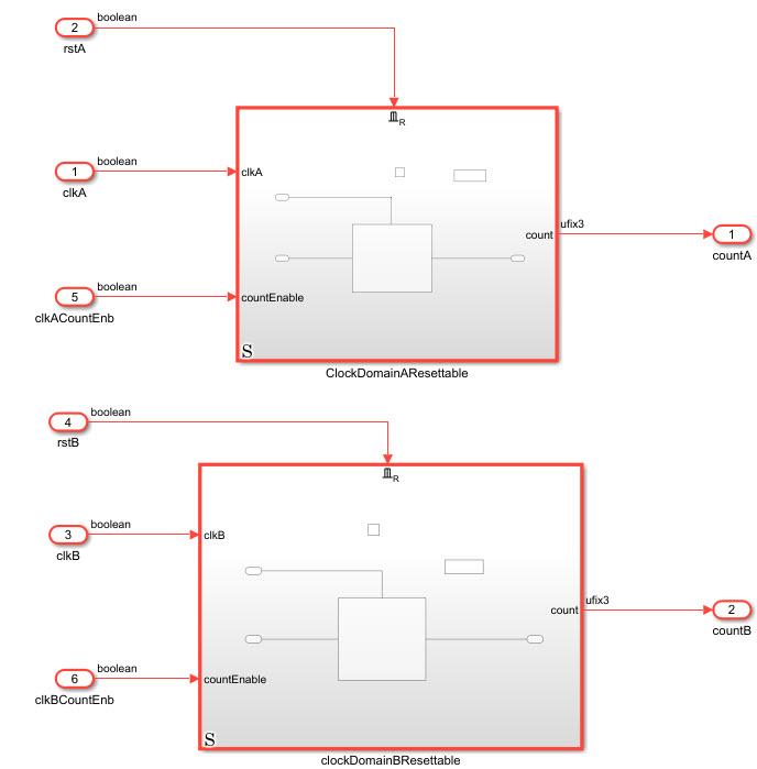
You can use triggered and resettable subsystems to explicitly represent clocks and resets as signals in Simulink. In this example, two pulse generators generate trigger signals with periods set to 2 and 4, respectively.
load_system('hdlcoderTriggerAsClockDemo');
open_system('hdlcoderTriggerAsClockDemo/DUT');
set_param('hdlcoderTriggerAsClockDemo', 'SimulationCommand', 'update');

Resettable subsystems model a reset port, while triggered subsystems model the clock signal. In this example, a triggered subsystem is placed within a resettable subsystem to achieve an asynchronous reset.
To enable the model to have a single reset signal from the resettable subsystem, minimize the global reset option. To minimize global resets, enable Minimize global resets in the HDL Code Generation > Global Settings > Ports tab of the configuration settings.
To use the trigger signal as a clock in your generated HDL code, enable the Use trigger signal as clock option in the HDL Code Generation > Global Settings > Ports tab. Then, generate the HDL code for the DUT subsystem using:
makehdl("hdlcoderTriggerAsClockDemo/DUT")### Working on the model hdlcoderTriggerAsClockDemo ### Generating HDL for hdlcoderTriggerAsClockDemo/DUT ### Using the config set for model hdlcoderTriggerAsClockDemo for HDL code generation parameters. ### Running HDL checks on the model 'hdlcoderTriggerAsClockDemo'. ### Begin compilation of the model 'hdlcoderTriggerAsClockDemo'... ### Begin compilation of the model 'hdlcoderTriggerAsClockDemo'... ### Working on the model 'hdlcoderTriggerAsClockDemo'... ### Working on... GenerateModel ### Begin model generation 'gm_hdlcoderTriggerAsClockDemo'... ### Copying DUT to the generated model.... ### Model generation complete. ### Generated model saved at hdlsrc/hdlcoderTriggerAsClockDemo/gm_hdlcoderTriggerAsClockDemo.slx ### Begin VHDL Code Generation for 'hdlcoderTriggerAsClockDemo'. ### Working on hdlcoderTriggerAsClockDemo/DUT/ClockDomainAResettable/ClockDomainA as hdlsrc/hdlcoderTriggerAsClockDemo/ClockDomainA.vhd. ### Working on hdlcoderTriggerAsClockDemo/DUT/ClockDomainAResettable as hdlsrc/hdlcoderTriggerAsClockDemo/ClockDomainAResettable.vhd. ### Working on hdlcoderTriggerAsClockDemo/DUT/clockDomainBResettable/ClockDomainB as hdlsrc/hdlcoderTriggerAsClockDemo/ClockDomainB.vhd. ### Working on hdlcoderTriggerAsClockDemo/DUT/clockDomainBResettable as hdlsrc/hdlcoderTriggerAsClockDemo/clockDomainBResettable.vhd. ### Working on hdlcoderTriggerAsClockDemo/DUT as hdlsrc/hdlcoderTriggerAsClockDemo/DUT.vhd. ### Code Generation for 'hdlcoderTriggerAsClockDemo' completed. ### Generating HTML files for code generation report at index.html ### Creating HDL Code Generation Check Report DUT_report.html ### HDL check for 'hdlcoderTriggerAsClockDemo' complete with 0 errors, 1 warnings, and 0 messages. ### HDL code generation complete.
HDL Coder generates HDL code that explicitly represents clocks and resets as signals as shown in this code snippet
ENTITY DUT IS
  PORT( clkA                              :   IN    std_logic;
        rstA                              :   IN    std_logic;
        clkB                              :   IN    std_logic;
        rstB                              :   IN    std_logic;
        clkACountEnb                      :   IN    std_logic;
        clkBCountEnb                      :   IN    std_logic;
        countA                            :   OUT   std_logic_vector(2 DOWNTO 0);  -- ufix3
        countB                            :   OUT   std_logic_vector(2 DOWNTO 0)  -- ufix3
        );
END DUT;
...
BEGIN
  u_ClockDomainAResettable : ClockDomainAResettable
    PORT MAP( clkA => clkA,
              countEnable => clkACountEnb,
              rstA => rstA,
              count => ClockDomainAResettable_out1  -- ufix3
              );

  u_clockDomainBResettable : clockDomainBResettable
    PORT MAP( clkB => clkB,
              countEnable => clkBCountEnb,
              rstB => rstB,
              count => clockDomainBResettable_out1  -- ufix3
              );
This method generates an additional level of hierarchy due to the nested subsystems. If you inspect the ClockDomainAResettable HDL Code you will see it contains the entity corresponding to the counter. To learn more about how to model asynchronous and synchronous resets see: Use Triggered Subsystem for Asynchronous Clock Domain.
Limitations
To generate multiple reset/clock pairs, you need two hierarchy levels in your design to add the reset and trigger control ports.