Optimize Clock Speed for MATLAB Code by Using Adaptive Pipelining
This example shows how to use the adaptive pipelining optimization in HDL Coder™ to optimize clock speed for a MATLAB® design.
Introduction
Certain patterns of code that have registers can improve the achievable clock frequency and reduce the area usage on FPGA boards. The adaptive pipelining optimization creates these patterns by inserting pipeline registers in your design. To determine the optimal number of pipeline registers to insert in your design, the target device, target frequency, and multiplier word lengths are considered.
You can also use adaptive pipelining for:
Automatically pipelining multiply operations for optimized Digital Signal Processors (DSP) mapping.
Other optimizations, such as resource sharing, which saves area and timing because HDL Coder shares resources and inserts adaptive pipeline registers.
To insert adaptive pipelining into your design:
Specify the target device by specifying a synthesis tool.
Set your target frequency to be greater than zero.
Enable Adaptive Pipelining in a MATLAB Design
Set adaptive pipelining by using an HDL code configuration object. For example, this MATLAB code creates an HDL code configuration object and sets the adaptive pipelining property to
true:
hdlcfg = coder.config('hdl');
hdlcfg.AdaptivePipelining = true;
For more information, see coder.HdlConfig.
Enable adaptive pipelining in the HDL Workflow Advisor > HDL Code Generation task > Optimization tab.
Adaptive Pipelining Example
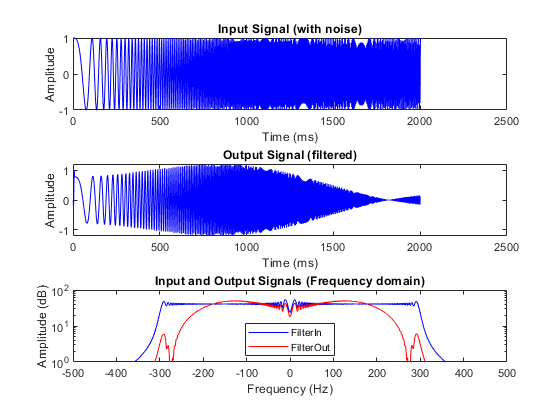
Consider the following example design of a simple symmetric FIR filter. Adaptive pipelining inserts pipelines to reduce the amount of combinatorial logic and increase the clock speed. The example also shows a MATLAB test bench that exercises the filter.
design_name = 'mlhdlc_sfir';
testbench_name = 'mlhdlc_sfir_tb';
Review the MATLAB design.
open(design_name);
%%%%%%%%%%%%%%%%%%%%%%%%%%%%%%%%%%%%%%%%%%%%%%%%%%%%%%%%%%%%%%%%%%%%%%%%%%
% MATLAB design: Symmetric FIR Filter
%
% Introduction:
%
% We can reduce the complexity of the FIR filter by leveraging its
% symmetry. Symmetry for an n-tap filter implies, coefficient h0 =
% coefficient hn-1, coefficient, h1 = coefficient hn-2, etc. In this case,
% the number of multipliers can be approximately halved. The key is to add
% the two data values that need to be multiplied with the same coefficient
% prior to performing the multiplication.
%
% Key Design pattern covered in this example:
% (1) Filter states represented using the persistent variables
% (2) Filter coefficients passed in as parameters

%   Copyright 2011-2026 The MathWorks, Inc.

%#codegen
function [y_out, delayed_xout] = mlhdlc_sfir(x_in,h_in1,h_in2,h_in3,h_in4)
% Symmetric FIR Filter

% declare and initialize the delay registers
persistent ud1 ud2 ud3 ud4 ud5 ud6 ud7 ud8;
if isempty(ud1)
    ud1 = 0; ud2 = 0; ud3 = 0; ud4 = 0; ud5 = 0; ud6 = 0; ud7 = 0; ud8 = 0;
end

% access the previous value of states/registers
a1 = ud1 + ud8; a2 = ud2 + ud7;
a3 = ud3 + ud6; a4 = ud4 + ud5;

% multiplier chain
m1 = h_in1 * a1; m2 = h_in2 * a2;
m3 = h_in3 * a3; m4 = h_in4 * a4;

% adder chain
a5 = m1 + m2; a6 = m3 + m4;

% filtered output
y_out = a5 + a6;

% delayout input signal
delayed_xout = ud8;

% update the delay line
ud8 = ud7;
ud7 = ud6;
ud6 = ud5;
ud5 = ud4;
ud4 = ud3;
ud3 = ud2;
ud2 = ud1;
ud1 = x_in;
end
Simulate the Design
Before you generate code, simulate the design by using the test bench to make sure there are no run-time errors.
mlhdlc_sfir_tb
Set Up Synthesis Tool Path
Before you use HDL Coder to generate code, set up your synthesis tool path to synthesize the generated HDL code. Use the hdlsetuptoolpath function. For example, if your synthesis tool is Xilinx® Vivado®:
hdlsetuptoolpath('ToolName','Xilinx Vivado','ToolPath',...
               vivadopath);
You must have already installed Xilinx Vivado. To check your Xilinx Vivado synthesis tool setup, start the tool by running this command:
!vivado
Create an HDL Coder Project
1. Create a project by running this command:
coder -hdlcoder -new fir_project
2. For MATLAB Function, add the MATLAB design mlhdlc_sfir. Add mlhdlc_sfir_tb.m as the MATLAB test bench.
3. Click Autodefine types and use the recommended types for the MATLAB design. HDL Coder infers data types by running the test bench.
Create Fixed-Point Versions of Algorithm and Test Bench
Click the Workflow Advisor button to open the Workflow Advisor. The Define Input Types task has passed.
Run the Fixed-Point Conversion task. The Fixed-Point Conversion tool opens in the right pane. For more information, see Floating-Point to Fixed-Point Conversion.
Select Code Generation Options
Before you generate HDL code, to deploy the code onto a target platform and use adaptive pipelining for your design, specify a synthesis tool. In the Code Generation Target task, leave Workflow set to Generic ASIC/FPGA and specify Xilinx Vivado as the Synthesis Tool. If you do not see the synthesis tool, click Refresh list. Specifying the Synthesis tool sets default values for the target hardware, such as Chip family, Device, Package, and Speed. Set Speed to -1. Leave the rest of the target hardware properties at their defaults.
To show the effects of adaptive pipelining, specify a target frequency that you are trying to achieve for your target device. For this example, set the Target frequency (MHz) to 200. Run this task.
In the HDL Code Generation task, by using the tabs on the right side of this task, you can specify additional code generation options. For this example, in the HDL Code Generation task > Optimization tab:
Specify
1for Input pipelining and Output pipelining.Set Loop Optimizations to Loop Unroll. It is good practice to enable this option whenever you are using adaptive pipelining.
For before and after comparison of adaptive pipelining effects on your design, keep the Adaptive Pipelining check box clear.
Click Run to generate HDL code.
Examine the log window and click the links to explore the generated code and the reports. In the log window, the report shows two cycles of latency, one cycle each for the input pipeline and output pipeline added.
Synthesize Generated Code for Nonoptimized Design
After generating HDL code, in this example, go to Synthesis and Analysis and clear skip this task so that synthesis and implementation can be run on your design by using your specified Synthesis Tool, Xilinx Vivado. HDL Coder synthesizes the HDL code on the target platform and generates area and timing reports for your design based on the target device that you specify.
To synthesize the generated HDL code and generate a timing report from synthesis:
1. Go to the Create project task and add the clock_constraint.xdc file from the example folder by either:
Providing the path to the file manually in the Additional Project Files option.
By selecting the file using the ellipsis on the right-side of the Additional Project Files option. Click the right side of the drop-down list for another ellipsis that opens your file explorer window. Navigate to the folder containing
clock_constraint.xdc, double-click the file, and click OK.
If you adjust your target frequency, adjust the clock constraint file accordingly. For example, because the target frequency is 200 MHz, and the clock constraint file requires the period in nanoseconds, the period is set to 1/200 MHz = 5 ns.
2. Run the Create project task.
This task creates a Xilinx Vivado synthesis project for the HDL code. HDL Coder uses this project in the next task to synthesize the design.
3. Select and run the Run Synthesis task.
This task starts the synthesis tool in the background, opens the synthesis project, compiles the HDL code, synthesizes the design, and generates netlists and area and timing reports. The timing reports take into account the clock_constraint.xdc file you previously specified to calculate slack between your required path delay and your actual path delay.
3. Select and run the Run Implementation task.
This task starts the synthesis tool in the background, runs place and route on the design, and generates pre- and post-route timing information for use in critical path analysis and back annotation of your source model.
The timing report in the output window of the Run Implementation task has the synthesis results show a negative slack of -2.47 ns, indicating that timing constraints are not met, and the clock frequency is 133 MHz, below the target frequency 200 MHz.
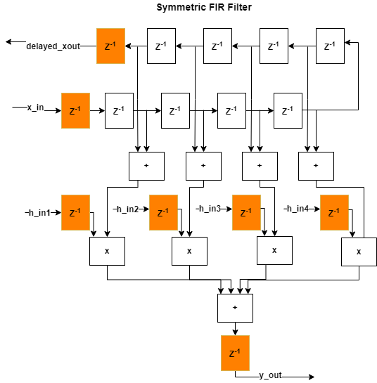
This figure shows how the algorithm is implemented in hardware when running synthesis on the generated code without adaptive pipelining. The input and output pipelines are shown in orange.
Generate and Synthesize Code for Optimized Design with Adaptive Pipelining
To generate HDL code with adaptive pipelining enabled, go to the HDL Code Generation task > Optimization tab, enable Adaptive Pipelining, and click Run.
In the log window, the report now shows four cycles of latency per output port, indicating that adaptive pipelining adds extra delays in the design.
When you run this task again, the subsequent tasks are reset. Because you have already specified your clock constraint file, right-click the Synthesis and Analysis task and select Run This task to run through the entire project creation, synthesis, and implementation workflow.
The timing report in the output window of the Run Implementation task has the synthesis results show a positive slack of .874 ns, indicating that timing constraints are now met as a result of enabling adaptive pipelining. The clock frequency is 242 MHz, above the target frequency 200 MHz.
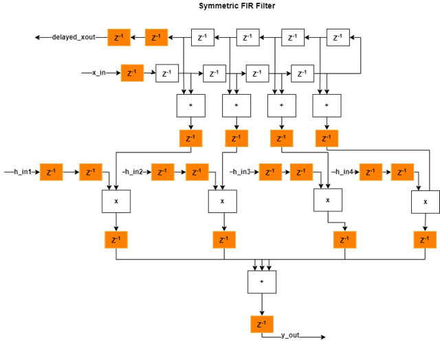
This figure shows how the algorithm is implemented in hardware when running synthesis on the generated code with adaptive pipelining on. The additional delays added from adaptive pipelining and delay balancing are shown in orange, along with the original input and output pipelines.
Limitations
While adaptive pipelining can improve clock frequency and reduce area usage for your design, multiply operations might not be pipelined when adaptive pipelining is enabled if:
The multiply operation is in a
forloop that is not unrolled.The multiply operation is in a subfunction and Generate instantiable code for functions is not enabled. Generate instantiable code for functions is located in the HDL Code Generation task > Advanced tab.
The multiply operation is in a subfunction and the function contains
coder.inline('never').
See Also
Pipelining MATLAB Code | Pipeline MATLAB Expressions | Optimize MATLAB Loops