Optimize Generated HDL Code for Multirate Designs with Large Rate Differentials
Issue
When generating HDL code from your multirate algorithm in Simulink®, HDL Coder™ might generate a large number of pipeline registers that can prevent the HDL design from fitting into an FPGA. This issue occurs due to modeling patterns that might result in large rate differentials. You can address this issue by using modeling techniques to manage sample time ratios.
Description
This issue occurs when your Simulink® model has a significantly large difference in sample rates or uses certain block implementations or optimizations that result in different clock-rate paths, such as:
Multicycle block implementations
Input and output pipelining
Distributed pipelining
Floating-point library mapping
Native floating-point HDL code generation
Fixed-point math functions such as reciprocal, sqrt, or divide
Resource sharing
Streaming
The additional pipelines result in a latency overhead that requires the insertion of matching delays across multiple signal paths operating at different rates. If the ratio of the fastest to the slowest clock rate is quite large, the code generator can potentially introduce a large number of registers in the resulting HDL code. The large number of pipeline registers can increase the size of the generated HDL files, and can prevent the design from fitting into an FPGA.
To see an example of how this issue occurs, open this Simulink model.
open_system('hdlcoder_multirate_high_differential')
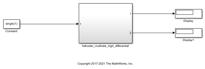
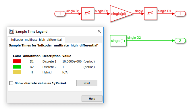
When you compile the model and double-click the hdlcoder_multirate_high_differential Subsystem, you can see that the model has a floating-point Gain block, a multicycle operator, in the fast clock-rate region.
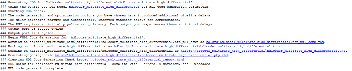
Generate HDL code for the hdlcoder_multirate_high_differential Subsystem and check the output log.
Open the generated model. At the command line, enter gm_hdlcoder_multirate_high_differential. When you compile the model and double-click the hdlcoder_multirate_high_differential Subsystem, the model looks as displayed by the sample time legend.
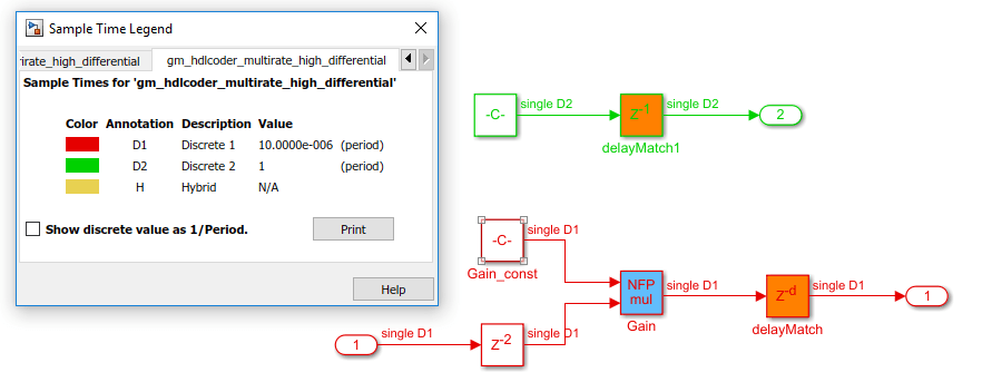
The large output latency on the fast clock rate region of the design is introduced by the code generator to balance delays across multiple output paths of the system. This large latency increases the size of the generated HDL files and reduces the efficiency of the generated code.
Recommendations
Recommendation 1: Use a Single-Rate Model
Most applications that you target the HDL code for might not require such a large rate differential. In that case, it is recommended that you use a single-rate model. In this example, you can change the sample rate of the Constant block inside the hdlcoder_multirate_high_differential subsystem to be the same as that of the base model.
Open this model that has the sample time of the Constant block changed to 10E-06, which is the same sample time as the base sample time of the model.
open_system('hdlcoder_singlerate')
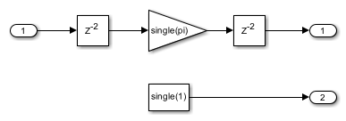
When you compile the model and double-click the hdlcoder_singlerate Subsystem, you see that the signal paths in the model operate at the same sample time of 10E-06.

Set UseFloatingPoint property to on for the hdlcoder_singlerate model by using the hdlset_param function. Generate HDL code for the hdlcoder_singlerate subsystem and check the output log.
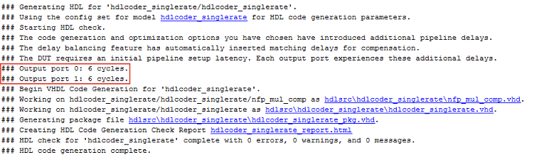
You see that the output latency has decreased significantly. Now open the generated model. At the MATLAB® command line, enter gm_hdlcoder_singlerate. When you compile the model and double-click the hdlcoder_singlerate Subsystem, the model looks as displayed by the sample time legend.
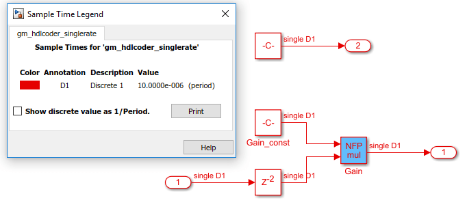
The generated HDL code is now optimal and uses few registers. Therefore, you can deploy the design to target FPGA platforms.
Recommendation 2: Reduce the Rate Differential
If you want to use a multirate model, it is recommended that you reduce the rate differential. Rate differential corresponds to the ratio of the fastest to the slowest clock rate in your design. If your target application requires two signal paths such that one signal path runs in time units of nanoseconds (ns) and the other signal path runs in time units of microseconds (us), you can choose to retain the multirate paths in your model. Be aware that delay balancing can introduce a significantly large number of registers to balance the signal paths.
In this example, you can change the sample rate of the Constant block inside the hdlcoder_multirate_high_differential Subsystem to reduce the rate differential.
Open this model that has the sample time of the Constant block changed to 0.01.
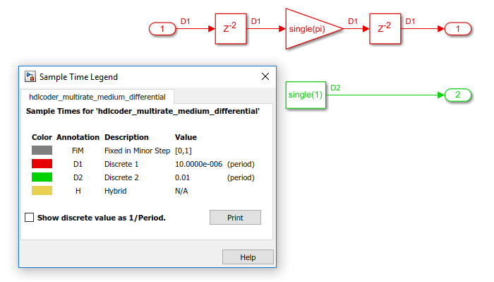
open_system ('hdlcoder_multirate_medium_differential')
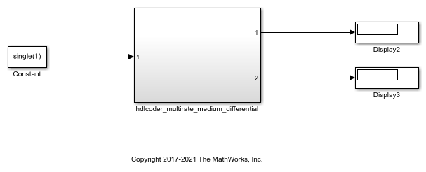
When you compile the model and double-click the hdlcoder__multirate_medium_differential Subsystem, you see that the rate differential between the two signal paths is equal to 1000.
Generate HDL code for the hdlcoder_multirate_medium_differential Subsystem and check the output log.
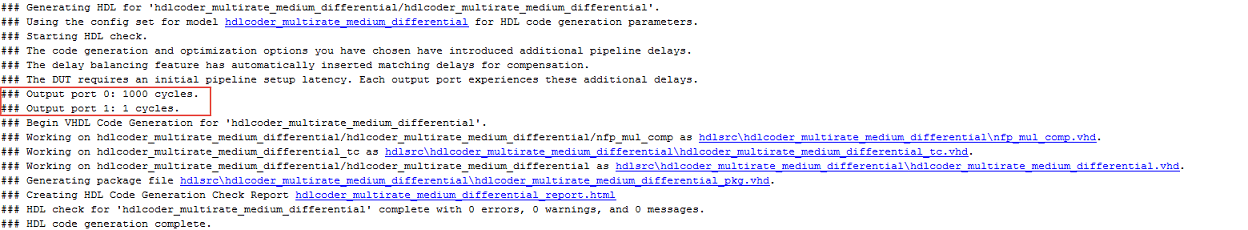
Open the generated model. At the MATLAB® command line, enter gm_hdlcoder_multirate_medium_differential. When you compile the generated model and double-click the hdlcoder_multirate_medium_differential Subsystem, the model is as displayed by the sample time legend.
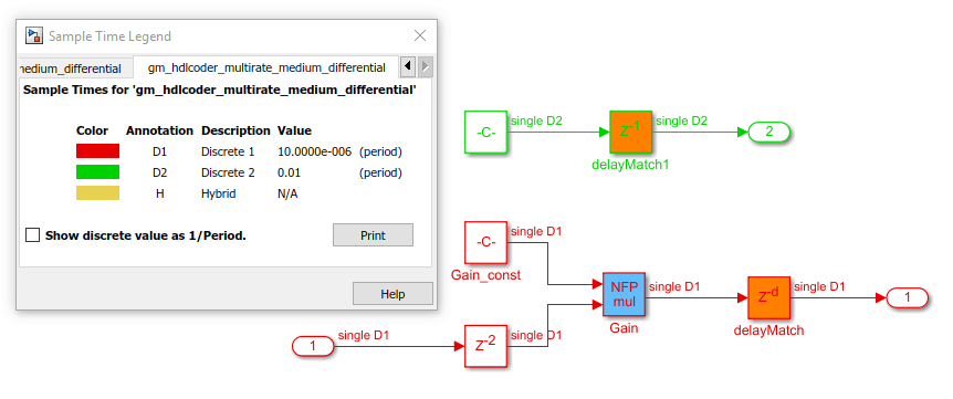
The model has a large number of registers, approximately 1000, in the fast clock rate path. The additional cost of registers is expected when you have a control logic that runs at a sample rate that is 1000 times faster than the sample rate of the system. When you deploy the generated code to a target platform, be aware of the constraints in hardware resources on the target platform. This recommendation offers a tradeoff between generating optimal HDL code and targeting practical FPGA applications that might require an extremely large rate differential.
Recommendation 3: Map Pipeline Delays to RAM
To optimize the number of registers that your design uses on the target FPGA device, you can use the Map Pipeline Delays to RAM setting. This setting is a tradeoff of the pipeline registers that are inserted in the HDL code with RAM resources to save area footprint on the target FPGA device. You can enable this setting in the HDL Code Generation > Optimizations > General tab of the Configuration Parameters dialog box.
You can also specify this setting at the command line by using the
MapPipelineDelaysToRAM property with
hdlset_param or makehdl. You can view the
property value by using hdlget_param. Use either of these methods.
Pass the property as an argument to the
makehdlfunction.makehdl('hdlcoder_multirate_high_differential/hdlcoder_multirate_high_differential', ... 'MapPipelineDelaysToRAM','on')When you use
hdlset_param, you can set the parameter on the model, and then generate HDL code by usingmakehdl.hdlset_param('hdlcoder_multirate_high_differential', ... 'MapPipelineDelaysToRAM','on') makehdl('hdlcoder_multirate_high_differential/hdlcoder_multirate_high_differential')
Use this setting in combination with the previous recommendations to further improve the efficiency of the generated HDL code and for deploying the code to the target platform.
See Also
createFloatingPointTargetConfig