Synchronization of Global Reset Signal to IP Core Clock Domain
The HDL DUT IP core and the Address Decoder logic in the AXI4 Slave interface wrapper of the HDL IP core are driven by a global reset signal. If you generate an HDL IP core without any AXI4 slave interfaces, HDL Coder™ does not generate the AXI4 slave interface wrapper. The global reset signal becomes the same as the IP core reset signal and drives the HDL IP core for the DUT. To learn how you can generate an IP core without AXI4 slave interfaces, see Generate Board-Independent HDL IP Core from Simulink Model.

When you generate the AXI4 slave interfaces in the HDL IP
core, the global reset signal is driven by three reset signals: the IP core external
reset, the reset signal of the AXI interconnect, and the soft reset which is asserted
when you write to the IPCore_Reset AXI register. For more
information, see Custom IP Core Report. The global reset signal in this case drives the
HDL IP core for the DUT and the Address Decoder logic in the AXI4
slave wrapper.

The IPCore_Clk and AXILite_ACLK must be connected
to the same clock source. The IPCore_RESETN and
AXILite_ARESETN must be connected to the same reset
source.
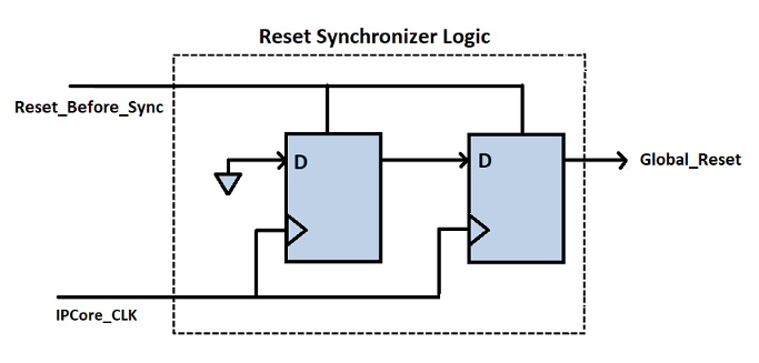
These reset signals can be either synchronous or asynchronous. Using asynchronous
reset signals can be problematic and result in potential metastability issues in
flipflops when the reset de-asserts within the latching window of the clock. To avoid
generation of possible metastable values when combining the reset signals, HDL Coder automatically inserts a reset synchronization logic, as indicated by the
Reset Sync block. The reset synchronization logic synchronizes
the global reset signal to the IP core clock domain. This logic is inserted when you
open the HDL Workflow Advisor and run the Generate RTL Code and IP
Core task of the IP Core Generation workflow.
The reset synchronization logic contains two back-to-back flipflops that are
synchronous to the IPCore_CLK signal. The flipflops make sure that
de-assertion of the reset signal occurs after two clock cycles of when the
IPCore_CLK signal becomes high. This synchronous de-assertion
avoids generation of a global reset signal that has possible metastable values.
The logic works differently depending on whether you specify the Reset
type as Synchronous or
Asynchronous on the model. If your Reset
type is Asynchronous, the synchronization
logic asserts the reset signal asynchronously and de-asserts the reset signal
synchronously. For example, this code illustrates the generated Verilog® code for the reset synchronization logic when you generate the IP core
with asynchronous reset.
...
...

reg_reset_pipe_process : PROCESS (clk, reset_in)
  BEGIN
    IF reset_in = '1' THEN
      reset_pipe <= '1';
    ELSIF clk'EVENT AND clk = '1' THEN
      IF enb = '1' THEN
        reset_pipe <= const_0;
      END IF;
    END IF;
  END PROCESS reg_reset_pipe_process;


  reg_reset_delay_process : PROCESS (clk, reset_in)
  BEGIN
    IF reset_in = '1' THEN
      reset_out <= '1';
    ELSIF clk'EVENT AND clk = '1' THEN
      IF enb = '1' THEN
        reset_out <= reset_pipe;
      END IF;
    END IF;
  END PROCESS reg_reset_delay_process;


END rtl;
If your Reset type is Synchronous, the
synchronization logic asserts and de-asserts the reset signal synchronously. For
example, this code illustrates the generated Verilog code for the reset synchronization logic when you generate the IP core
with synchronous reset.
...
...

reg_reset_pipe_process : PROCESS (clk)
  BEGIN
    IF clk'EVENT AND clk = '1' THEN
      IF reset_in = '1' THEN
        reset_pipe <= '1';
      ELSIF enb = '1' THEN
        reset_pipe <= const_0;
      END IF;
    END IF;
  END PROCESS reg_reset_pipe_process;


  reg_reset_delay_process : PROCESS (clk)
  BEGIN
    IF clk'EVENT AND clk = '1' THEN
      IF reset_in = '1' THEN
        reset_out <= '1';
      ELSIF enb = '1' THEN
        reset_out <= reset_pipe;
      END IF;
    END IF;
  END PROCESS reg_reset_delay_process;


END rtl;