Build Custom Linux Image for HDL Coder IP Core
This example shows how to build a custom Linux® image for an HDL Coder IP core by using the MathWorks® build system for the Digilent Zybo Z7-10 Zynq® board. The example also demonstrates how to set up the build environment and create a Linux image for the Digilent Zybo Z7-10 Zynq board. You can use the same process to create Linux image for other Zynq platforms.
The MathWorks build system is a tool that generates custom Linux images through cross-compilation. The MathWorks build system wraps the buildroot in pre- and post-processing scripts to automate the generation of system images for various platforms. The build system uses scripts that take the target board, platform, or image description file as an input and output a complete system image, including the boot loaders, kernel, and user space.
Requirements
Debian®-9 Linux Operating System (OS).
Xilinx® Vivado® Design Suite. Use a version listed in the HDL Language Support and Supported Third-Party Tools and Hardware.
MathWorks build system.
Digilent Zybo Z7-10 Zynq development board and accessory kit.
Install Debian-9 Linux Operating System
To run this example, you require a Debian-9 Linux OS. If you already have Debian-9 Linux OS installed, skip this step.
To install Debian-9 OS:
Download the Debian-9 CD image ISO file. To download a CD image from Debian website, see Debian-9 Download on the Debian website. Download
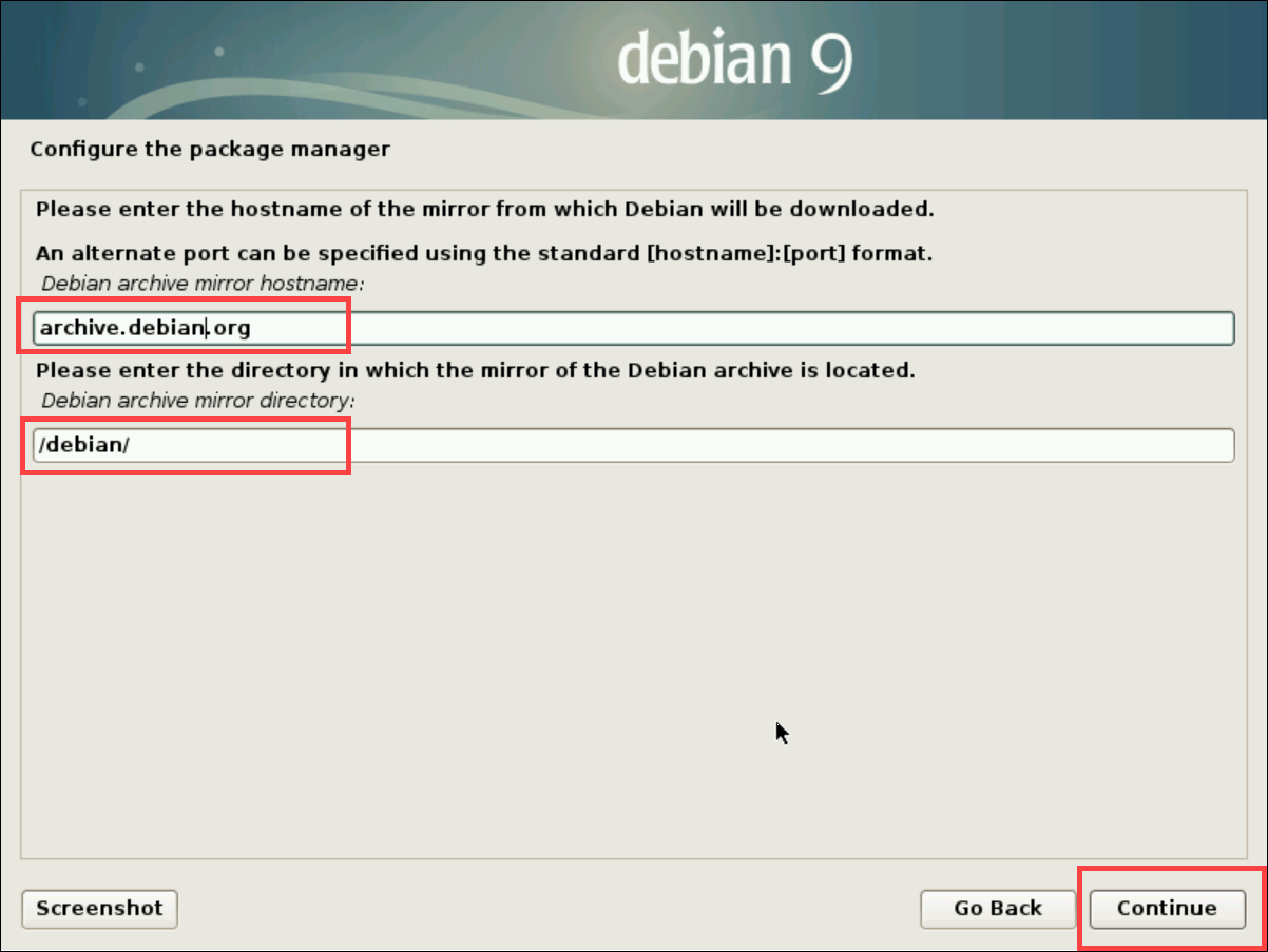
debian-9.13.0-amd64-netinst.isofile.Install Debian-9 by using the ISO file. During installation, in the Configure the package manager step, set the Debian archive mirror country option to
enter information manuallyto enter archive mirror manually. Click Continue.Set the Debian archive mirror hostname option to
archive.debian.organd Debian archive mirror directory option to/debian/. Click Continue to complete installation process. Ignore the error message that says "security.debian.org could not be accessed as there are no security updates for debian Lenny".Complete the Debian-9 installation.


Generate Hand-off Files Using Xilinx Vivado
Before you begin the build process, you must generate hand-off files by using the Xilinx Vivado and AMD Vitis® tools.
To generate the hand-off files, create a reference design using the Xilinx Vivado project. To create a reference design, follow the steps in the Create and Export a Custom Reference Design by Using Xilinx Vivado section in Define Custom Board and Reference Design for AMD Workflow. When creating a reference design, Xilinx Vivado project exports the settings for the Zynq processing system IP, such as the address mapping of memory and peripherals.
After you create the reference design, export the hardware platform from the Vivado block design and extract the header files from the Xilinx source archive (XSA) file by following these steps:
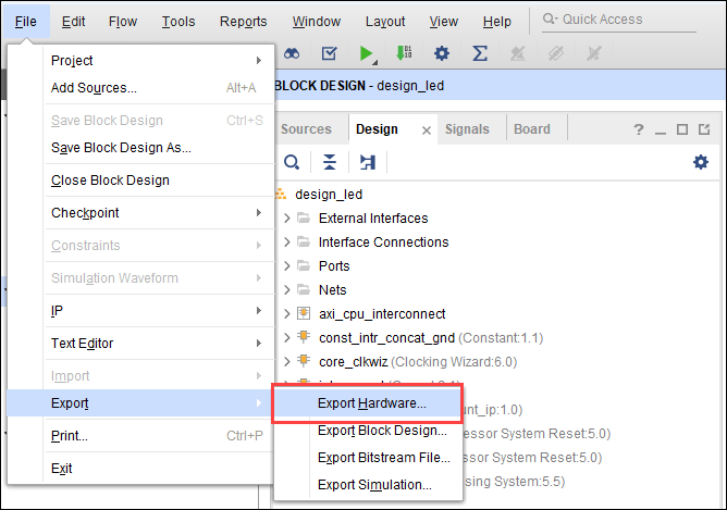
In the Vivado tool, open the block design in Vivado. On the File tab, select Export > Export Hardware. The Export Hardware Platform window opens.
In the Export Hardware Platform window, enter the XSA file name and export path. Click Next. Xilinx Vivado tool populates the export path with XSA File Name
.xsa.Extract the processor configured header files from the XSA file. To extract header files, navigate to the exported XSA file path in MATLAB®, and enter unzip command with your XSA file name. For example:
unzip design_led_wrapper.xsa

Build Zynq Linux Image Using MathWorks Build System
The MathWorks Buildroot repository on the GitHub® hosts the buildroot framework that creates the Xilinx Zynq platform and Altera® SoC SD card images for MathWorks tools. The build process involves setting up the necessary tools, loading hand-off files to the buildroot directory, build image using script and loading image to the SD card. You also need to install additional packages based on your requirement. For more information on the required packages, see buildroot packages.
Build the Zynq Linux image using the MathWorks build system by following these steps:
Setup Cross Compiler
To set up the cross compiler, install the Linaro ARM toolchain on your Linux machine. To download the Linaro Toolchain tarball file from the Linaro repository, see Linaro Binaries and download the gcc-linaro-6.3.1-2017.02-x86_64_arm-linux-gnueabihf.tar.xz file. Unzip the tarball file and copy the contents to the /opt/linaro/aarch32-6.3.1-2017.02 folder on your Linux machine.
Clone MathWorks Buildroot Repository
Clone the MathWorks buildroot repository by running this command:
git clone https://github.com/mathworks/buildroot.git
2. Checkout the mathworks_buildroot branch.
git checkout mathworks_buildroot
Transfer Generated Hand-Off Files into Buildroot Directory
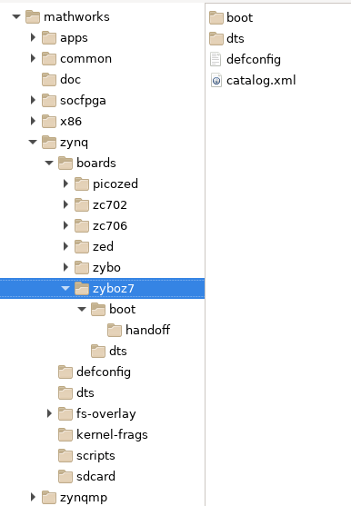
Copy the generated ps7_init_gpl.c and ps7_init_gpl.h files to the buildroot/board/mathworks/boards/zynq/zyboz710/handoff folder in the zyboz710 buildroot directory on your Debian-9 Linux machine.
Run Build Script
Build the Linux SD card image for the specific board by using this Python® build script command:
>> ./build.py -c board/mathworks/zynq/boards/zyboz710/catalog.xml
When required, install additional packages like gcc, make, or g++ by using sudo commands.
To provide a different path for the toolchain, use this build command:
>> ./build.py -p zynq -b zyboz710 --brconfig
BR2_TOOLCHAIN_EXTERNAL_PATH='/opt/linaro/aarch32-6.3.1-2017.02'
When the Linux image builds, the generated image is a ZIP file with name <board_name>_sdcard_hdlcoder_<build_date>.zip under the /buildroot/output/<board_name>_linux_linaro/images folder. To view the content of the image file, extract the <board_name>_sdcard_hdlcoder_<build_date>.zip file. The board_name and build_date denote the name of your hardware board and date of the build.
Load Linux Image into SD Card
Copy the contents of the ZIP folder to the SD card and insert the SD card into the Zybo Z7-10 board. Ensure that you set the board to SD boot mode by using the JP5 jumper switch. For more information about board connections, see Define Custom Board and Reference Design for AMD Workflow.
When you turn on the board, the PuTTY™ console displays a successful boot login. This ensures that the Linux image is loaded on the hardware board.

See Also
HDL Language Support and Supported Third-Party Tools and Hardware
Topics
- Define Custom Board and Reference Design for AMD Workflow
- Get Started with IP Core Generation from Simulink Model