Single-Acting Rotary Actuator (IL)
Single-acting rotary actuator in an isothermal liquid system

Libraries:
Simscape /
Fluids /
Isothermal Liquid /
Actuators
Description
The Single-Acting Rotary Actuator (IL) block models a rotary actuator that converts liquid pressure into mechanical torque in an isothermal liquid network. The motion of the piston when it is near full extension or full retraction is limited by one of four hard stop models.
Port A is the isothermal liquid conserving port associated with inlet
of the liquid chamber. Ports R and C are the
mechanical rotational conserving ports associated with the rotating shaft and the
actuator casing, respectively. If Mechanical orientation is set to
Pressure at A causes positive rotation of R relative to
			C
, the pressure in the liquid chamber causes a positive rotation of the
shaft at port R relative to port C. When the
shaft angle is calculated internally, the physical signal port q
reports the angle. When the angle is set by a connection to a Simscape™
Multibody™ joint, it is received as a physical signal at port
q.
Displacement
The piston displacement is measured as the position at port R relative
to port C. The Mechanical orientation
identifies the direction of piston displacement. The piston displacement is neutral,
or 0, when the chamber volume is equal to the Dead
volume. When displacement is received as an input, ensure that the
derivative of the position is equal to the piston velocity. This is automatically
the case when the input is received from a Rotational Multibody Interface block
connection to a Simscape Multibody joint.
Hard Stop Model
To avoid mechanical damage to an actuator when it is fully extended or fully retracted, an actuator typically displays nonlinear behavior when the piston approaches these limits. The Single-Acting Rotary Actuator (IL) block models this behavior with a choice of four hard stop models, which model the material compliance through a spring-damper system. The hard stop models are:
Stiffness and damping applied smoothly through transition region, damped rebound.Full stiffness and damping applied at bounds, undamped rebound.Full stiffness and damping applied at bounds, damped rebound.Based on coefficient of restitution
The hard stop force is modeled when the piston is at its upper or lower bound. The boundary region is within the Transition region of the Stroke or piston initial displacement. Outside of this region,
For more information about these settings, see the Rotational Hard Stop block page.
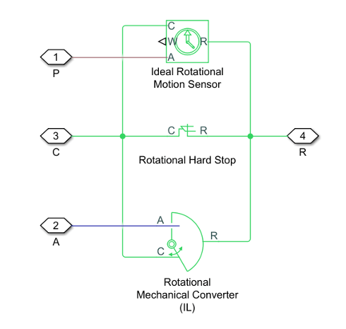
Block Schematics
The actuator block comprises three Foundation Library blocks:
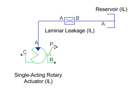
Leakage
Laminar leakage is not accounted for in the Single-Acting Rotary Actuator
(IL) block. To include leakage in your simulation, set the
Cross-sectional geometry parameter to
Custom and connect port A to
port A of the Laminar Leakage (IL) block.
Connect port B of the Laminar Leakage (IL) block to a Reservoir (IL)
block.
Examples
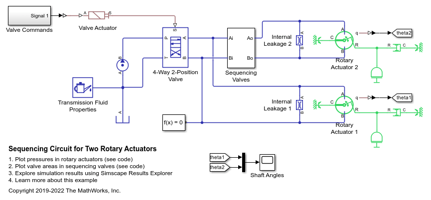
Sequencing Circuit for Two Rotary Actuators
A sequencing circuit that is based on four check valves installed in the pressure and return lines of the second rotary actuator. The cracking pressure of the meter-in check valves is set high enough to prevent flow into rotary actuator 2 while rotary actuator 1 is rotating, but lower than the pressure that develops once rotary actuator 1 reaches its hard stop. As a result, rotary actuator 2 starts moving only after rotary actuator 1 completes its stroke.