Design Optical System Using Optical System Designer
This example shows how to design an optical system using the Optical System Designer app. The Optical System Designer app enables you to design, modify, simulate, and analyze optical systems. Using the app, you can:
Create a new optical system or load an existing optical system from a ZMX file or the MATLAB® workspace.
Visualize the optical system in 2-D or 3-D.
Design a new optical system using various components, materials, and light sources, or modify an existing optical system.
Simulate ray tracing, and focus the optical system.
Analyze the optical system using spot diagrams, ray and chromatic aberration analysis, lens distortion analysis, and field curvature analysis.
Export the designed optical system as an
opticalSystemobject to the workspace or as a function you can use to create similar optical systems.
For information on how to analyze an optical system using the app, see Analyze Optical System Using Optical System Designer.
Open the Optical System Designer App
Open the Optical System Designer app from the Apps tab on the MATLAB Toolstrip, under Image Processing and Computer Vision, by selecting the Optical System Designer icon. You can also open the app by using the opticalSystemDesigner command at the MATLAB command prompt.
Create or Import Optical System
You can create a new optical system from scratch or import an existing optical system from an opticalSystem object or ZMX file.
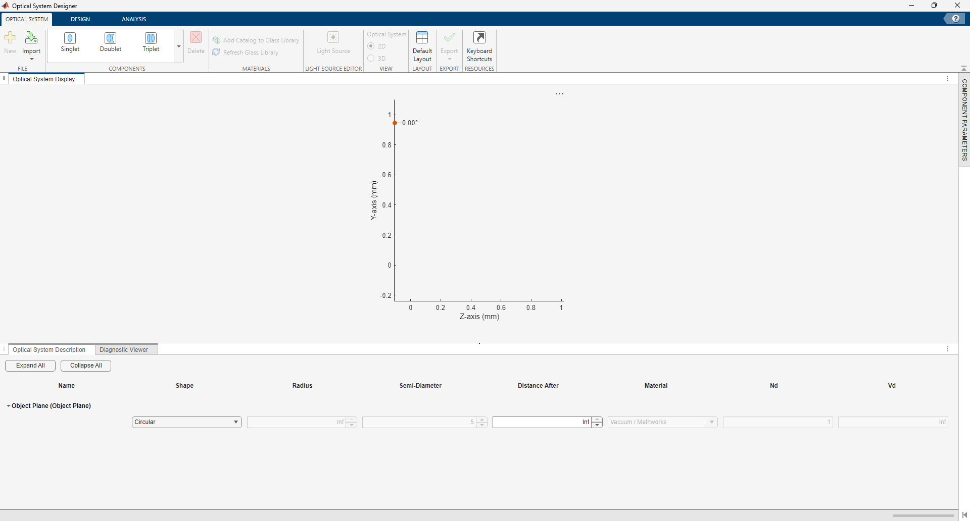
Create Optical System
To create a new optical system, on the Optical System tab of the app toolstrip, select New to open an empty canvas to which you can add optical elements.
Import Optical System
Alternatively, to import an existing optical system, select Import on the Optical System tab of the app toolstrip. Then select one of these options.
To import an optical system from a ZMX file, select From ZMX File. Then, in the dialog box, select your ZMX file.
To import an optical system from the workspace, select From Workspace. Then, in the dialog box, select your
opticalSystemobject.
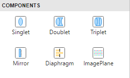
Add and Manage Components
You can add components to the optical system from the Components section of the Optical System tab of the app toolstrip. The available components are Singlet, Doublet, Triplet, Mirror, Diaphragm, and Image Plane. When you add a component, the app inserts the new component after the currently selected surface or component. By default, the app selects the last surface of the most recently added component. You can also add components by using the right-click context menu in the Optical System Description pane.
To delete a component, select the component and, in the Components section of the Optical System tab of the app toolstrip, select Delete. Alternatively, you can remove the component by using the right-click context menu of the component in the Optical System Description pane.
Edit Surface and Component Parameters
You can edit the parameters of the surfaces of the components in the Optical System Description pane. For each surface of a component, you can specify the Shape, Radius, Semi-Diameter, Distance After, Material, Nd (refractive index), and Vd (Abbe number). You can specify the material either using the Optical Material Picker available by setting the Material parameter or by directly entering Nd and Vd values.
You can modify the parameters of a surface or component using the collapsible options on the right side of the app window. To access these options, select a surface or component in the system and click Surface Parameters or Component Parameters, respectively. You can adjust the Name, Position, and Tilt Angles parameters for both surfaces and components. For surfaces, you can additionally set Shape Parameters and Conic and Aspheric Parameters.
Manage Optical Materials
You can add new optical materials to the glass library, enabling you to access them repeatedly in the Optical Material Picker. To add a glass catalog to the glass library, select Add Catalog to Glass Library. In the Select Catalog File dialog box**,** select the AGF file for the catalog you want to add to the library, and then click Open. Finally, in the app toolstrip, select Refresh Glass Library.
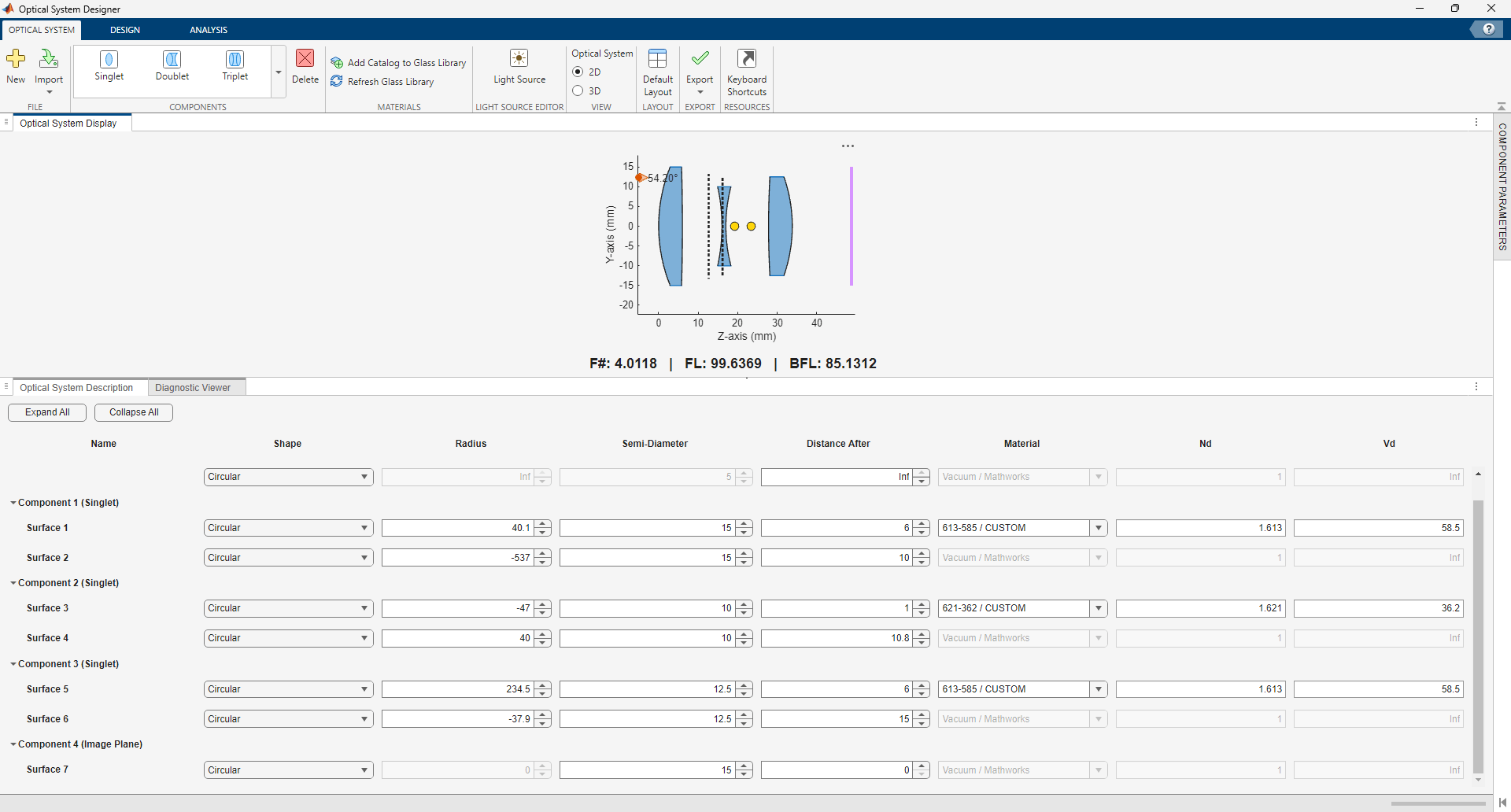
Construct a Cooke Triplet
Construct a Cooke triplet by adding three Singlet components and an Image Plane to your optical system, and then specify these parameters for their surfaces.
First lens (biconvex lens)
Surface 1 — Specify the Shape as
Circular, Radius as40.1, Semi-Diameter as15, Distance After as6, Nd as1.613, and Vd as58.5.Surface 2 — Specify the Shape as
Circular, Radius as-537, Semi-Diameter as15, Distance After as10, and Material asVacuum, as this is the closing surface of the lens.
Second lens (biconcave lens)
Surface 3 — Specify the Shape as
Circular, Radius as-47, Semi-Diameter as10, Distance After as1, Nd as1.621, and Vd as36.2.Surface 4 — Specify the Shape as
Circular, Radius as40, Semi-Diameter as10, Distance After as10.8, and Material asVacuum, as this is the closing surface of the lens.
Third lens (biconvex lens)
Surface 5 — Specify the Shape as
Circular, Radius as234.5, Semi-Diameter as12.5, Distance After as6, Nd as1.613, and Vd as58.5.Surface 6 — Specify the Shape as
Circular, Radius as-37.9, Semi-Diameter as12.5, Distance After as15, and Material asVacuum, as this is the closing surface of the lens.
Image plane
Surface 7 — Specify the Shape as
Circular, Semi-Diameter as15, and Distance After as0, as this is the last surface of the optical system.
Define Light Source
To define the light source, on the Optical System tab of the app toolstrip, in the Light Source Editor section, select Light Source.
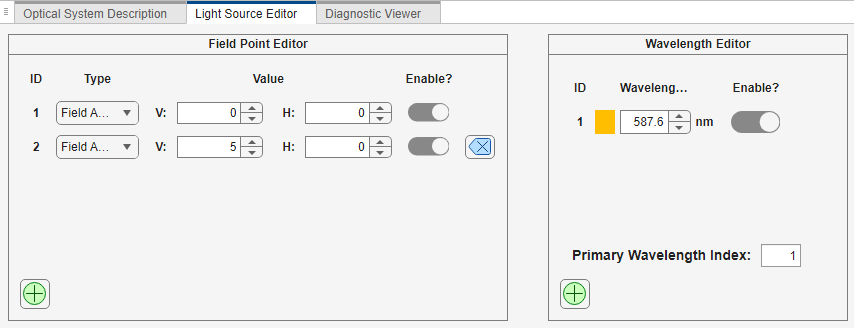
Field Point Editor
In the Light Source Editor pane, you can add or remove field points, and enable or disable specific field points in the Field Point Editor. You can define field points using one of these options.
Set Type to
Field Angleand specify the vertical angle V and horizontal angle H.Set Type to
Image Referenceand specify the 2-D coordinates X and Y.Set Type to
Object Referenceand specify the 2-D coordinates X and Y.Set Type to
Globaland specify the 3-D coordinates X, Y, and Z.
For more information about field points, see the fieldPoint object.
For the Cooke triplet, define two field points of Type Field Angle. Add the second field point by selecting the green plus icon in the bottom-left corner of the Field Point Editor.
Define the first field point with field angle values V
= 0and H= 0.Define the second field point with field angle values V
= 5and H= 0.
Wavelength Editor
In the Light Source Editor pane, you can add or remove wavelengths, and enable or disable specific wavelengths, in the Wavelength Editor. Specify wavelengths, in nanometers, and set the index of the primary wavelength.
For the Cooke triplet, define a single wavelength of 587.5618 nm. If the Wavelength Editor contains additional wavelengths, select the blue cross icon next to them to delete them.
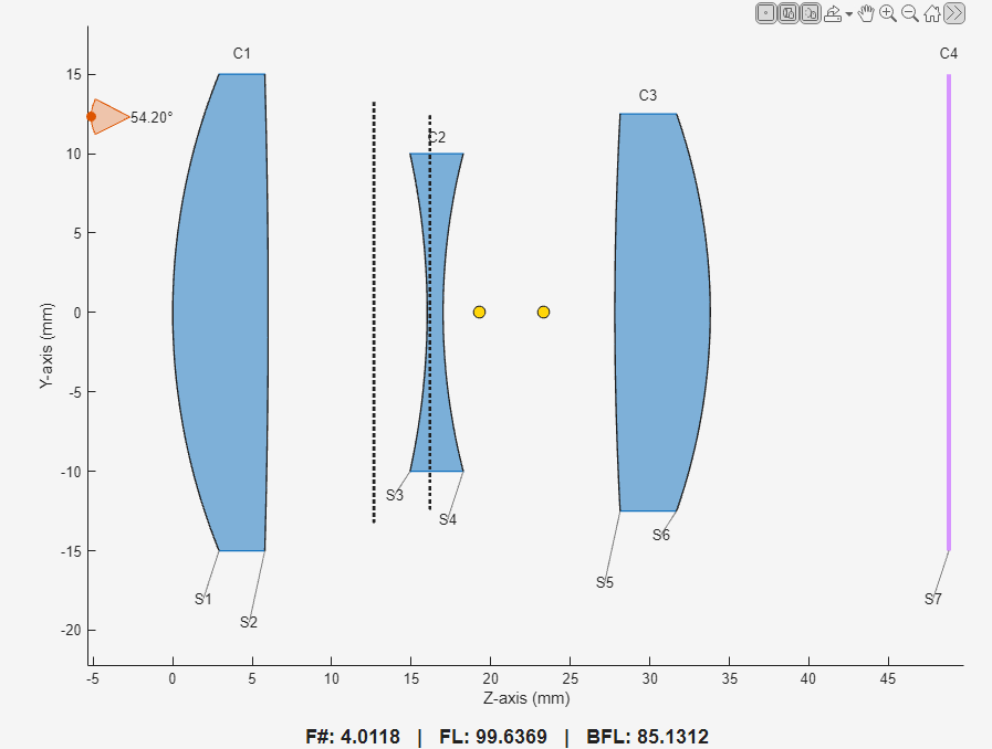
Visualize Optical System
The Optical System Display pane visualizes the optical system. The display also shows paraxial quantities like the F-number (F#), focal length (FL), and back focal length (BFL), as well as representations of the field points, entrance pupil, exit pupil, and the first and second principal points. You can toggle the visibility of field points, component labels, and surface labels using the axes toolbar.
In the View section of the Optical System tab, you can switch between 2-D and 3-D visualizations.
Apply Aperture Constraints
You can modify the optical system to satisfy aperture constraints such as working F-number, diaphragm radius, or entry pupil radius. Because these parameters are related, you can modify only one constraint at a time. On the Design tab of the app toolstrip, in the Aperture Constraints section, select the parameter for which to apply a constraint by setting Type, and then enter the desired Value for the constraint. You can also specify the Target Field Angle for the constraint. The app updates the Semi-Diameter parameter of surfaces and consequently the visualization.
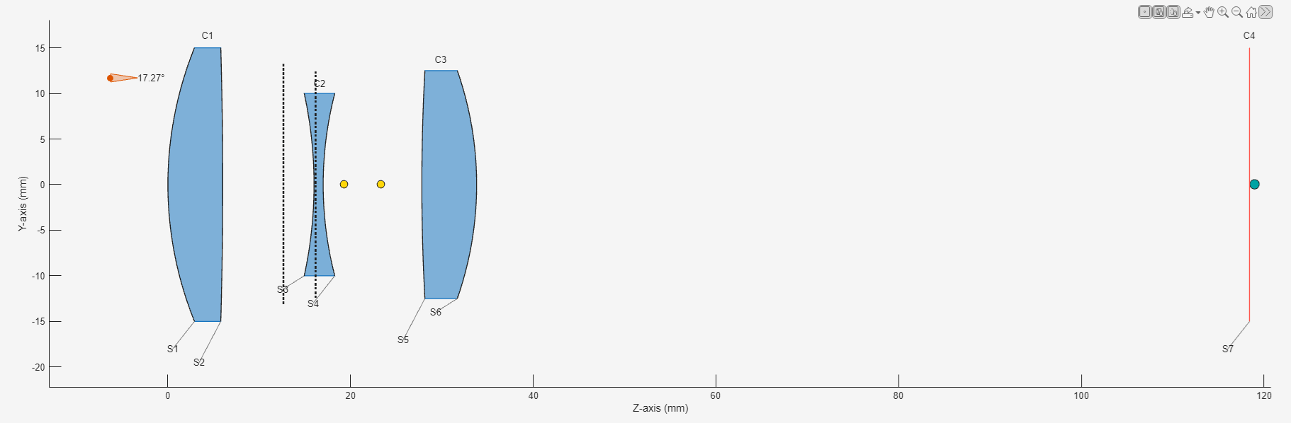
Focus the Optical System
To focus the optical system, on the Design tab of the app toolstrip, in the Focus section, select Auto Focus. The app focuses the optical system using the focus function, which updates the Distance After parameters of the surfaces, and thus the visualization, to focus the system.
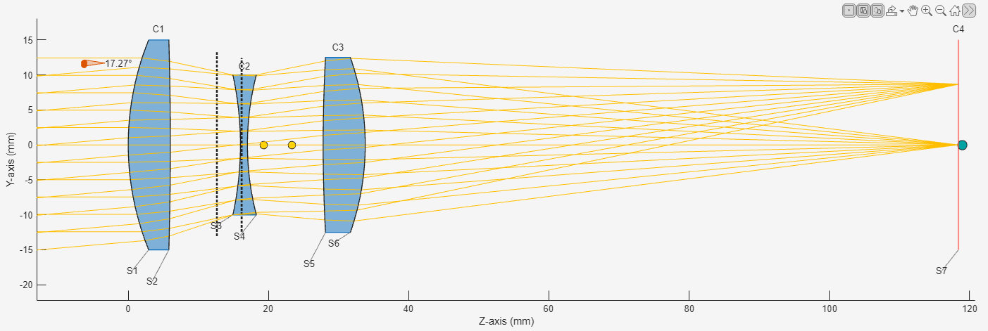
Select Trace Rays on the Analysis tab of the app toolstrip, and observe that the rays converge at the focal point on the image plane. The app traces rays for all combinations of enabled field points and wavelengths.
Export Optical System
Validate your optical system design throughout the design process by checking the logs in the Diagnostic Viewer pane. Once you resolve all issues in the Diagnostic Viewer, you can export the optical system using one of these options.
To export the optical system as an
opticalSystemobject to the workspace, on the Optical System tab of the app toolstrip, select Export and then select To Workspace.To export the optical system design as a function that you can use to create similar optical systems, select Export and then select To Function.