Customize Motor Control Algorithm for Different Hardware
This topic shows you how to customize a Simulink®-based motor control algorithm for a different inverter, motor, or processor.
Motor Control Blockset™ includes reference examples that support auto-deployment (deployment with pre-configured device drivers) on supported hardware, algorithm export capability, as well as generic (ANSI C) code generation for simulation-centric examples.
For details about examples customized for auto-deployment to supported microcontrollers, FPGAs, and real-time systems, see Hardware-Specific Code Generation. For details about examples without pre-configured auto-deployment capabilities, which are suitable for generic C code generation including algorithm export for custom hardware, see Generic (ANSI C) Code Generation.
If you want to use an example that supports auto-deployment, however, the hardware that you are using is different than the one supported by the example by default, you can use this workflow to customize such an example (or a Simulink-based motor control algorithm) for your hardware. You can use this workflow to modify such an example or algorithm for changes in the following hardware peripherals:
Inverter
Motor
Processor
The topic uses the sample model F28379dTargetMotorControlFOCQEP.slx
that the reference example Generate Motor Control Models for Selected Algorithm and Hardware generates (using the
TI F28379D Launchpad hardware target and FOC
QEP control algorithm) to demonstrate the workflow. For more details,
click the link to see the example documentation.
Modify Inverter
This section explains the workflow to change the inverter that a Simulink-based motor control algorithm uses.
Scenario 1: Pin Connections Between Inverter and Processor Remain Same
In this scenario, the pin connections between the inverter and processor remains unchanged even after replacing the inverter. However, after replacing the inverter, the inverter rating and other sensor circuits can change.
Ensure that the PWM frequency used in the motor control algorithm is compatible with the new inverter. For example, to customize the sample model
F28379dTargetMotorControlFOCQEP.slxaccording to the new inverter, update the target.PWM_frequency variable in the model initialization scriptF28379dTargetMotorControlData.massociated with the model.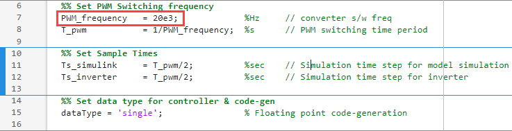
Update the inverter parameters according to the new inverter. For example, update the following variables in the model initialization script used by the sample model:
inverter.V_dc — Update the DC link voltage for the new inverter (V).
inverter.AMPPerCount — Update the phase current that is equivalent to one ADC count (A). This value can be positive or negative based on the current sense configuration of the new inverter.
If the current sense amplifier senses the current entering the motor as positive, this value is positive. If the current sense amplifier senses the current entering the motor as negative, this value is negative.
inverter.VoltPerCount — Update the voltage sensed per ADC count for the new inverter (V).
inverter.ISenseMax — Update the maximum measurable peak-neutral current by the current sensing circuit of the new inverter (A).
inverter.Rds_on — On-state resistance of MOSFETs of the new inverter (ohms).
inverter.Rshunt — Shunt resistance of the new inverter (ohms).
For more details about these parameters, see Model Initialization Script.
Scenario 2: Pin Connections Between Inverter and Processor Change
In this scenario, the pin connections between the inverter and processor change after replacing the inverter.
Follow the workflow steps for scenario 1. Afterwards, follow this procedure to reconfigure the pins to use the right hardware peripherals by updating the configuration settings of the Simulink model containing motor control algorithm.
For example, follow this procedure for the sample model
F28379dTargetMotorControlFOCQEP.slx:
Right-click the Simulink model canvas and select Model Configuration Parameters to open the Configuration Parameters window.
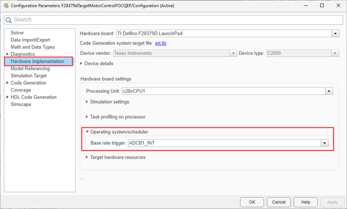
If you have set the base timer of the Simulink model to ADC interrupt, set the base timer to use the correct ADC interrupt (according to the newly selected ADC channel).
Navigate to the Operating system/scheduler section of the Hardware Implementation tab and set the Base rate trigger to use the appropriate ADC interrupt.
If the control algorithm uses ADC interrupts to trigger the scheduler and the ADC channels for measuring Ia and Ib currents change, configure the ADC blocks to use the right channels according to the new hardware configuration.
Similarly, update the configuration settings for the ADC channels for VDC and VABC voltages.
Use the ADC_C and ADC_D tabs of the Target hardware resources section to update these settings.
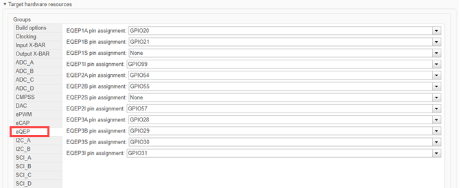
Update the pin configuration for the position sensor interface.
For example, use the eQEP tab of the Target hardware resources section to update the pin configuration for the quadrature encoder sensor as shown in the following figure.
Select the correct PWM channels for PWM phase a, b, and c.
Use the ePWM tab of the Target hardware resources section to update these settings.

If you have modeled an enable pin for inverter, configure the pin correctly according to the new inverter.
Scenario 3: Same Processor Used with Different Hardware Schematic and Inverter
In this scenario, you use a custom hardware with a processor that is identical to the one used by the Simulink model containing the motor control algorithm, however, the hardware has a different schematic and uses a different inverter.
To address such a change, follow the workflow for scenario one or two according to the new hardware schematic.
Modify Processor
This section explains the workflow to change the processor architecture that a Simulink-based motor control algorithm uses.
Identify an existing processor supported by the reference example Generate Motor Control Models for Selected Algorithm and Hardware that has an architecture close to the new processor.
For example, select the
TI F28379D Launchpadhardware target.Create a copy of the base hardware model
F28379dTargetMotorControl.slxfor theTI F28379D Launchpadhardware target to use the existing processor architecture as a base.Follow the instructions for Scenario 2 of the Modify Inverter section to update the configuration settings of the copied base hardware model according to the new processor. In addition, update the device drivers for the new processor.
Rename the model appropriately and save it as a new base hardware model.
Use the MATLAB® command prompt to run the
mcbAddHardwareToListfunction by using the new base hardware model name (that you used in step 3) as the modelName argument. For details about running this function, see Add Hardware Option to List section of the example live script.After you run the
mcbAddHardwareToListfunction, the HardwareTarget field in the live script shows the new processor (hardware). Select the newly added hardware target.Run the
mcbOpenExamplefunction to generate and open the target model for the new processor (target hardware) and a selected control algorithm. For details about running the function, see the Find and Open Models section of the example live script.
Modify Motor
This section explains the workflow to change the motor that a Simulink-based motor control algorithm uses.
To change the default motor used by an algorithm, you must update the motor parameters that an algorithm uses for initialization at run-time. For example, each target model that the Generate Motor Control Models for Selected Algorithm and Hardware reference example live script generates uses the following two scripts for initialization at run-time.
Hardware initialization script
Algorithm initialization script
The algorithm initialization script initializes the control algorithm related parameters, which includes the motor parameters.
For example, to use the sample model
F28379dTargetMotorControlFOCQEP.slx with a different motor, follow
this procedure to update the motor parameters available in the algorithm initialization
script associated with the model.
Open the algorithm initialization script
mcbFocQepData.massociated with the sample model.Update the following parameters in the algorithm initialization script.
pmsm.p — Number of pole pairs of the permanent magnet synchronous motor (PMSM)
pmsm.I_rated — Rated current of the PMSM (in amperes)
pmsm.N_rated — Rated speed of the PMSM (in RPM)
pmsm.Rs — Stator resistance of the PMSM (in ohms)
pmsm.Ld — D-axis inductance of the PMSM (in henries)
pmsm.Lq — Q-axis inductance of the PMSM (in henries)
pmsm.J — Inertia of the PMSM (in Kg-m2)
pmsm.B — Friction coefficient of the PMSM (in Kg-m2/s)
pmsm.Ke — Back EMF constant of the PMSM (in Vpk_LL/krpm, where Vpk_LL is the peak voltage line-to-line measurement)
pmsm.QEPIndexPresent — Specify one of the following values:
true— Indicates that the quadrature encoder sensor uses an index pulse. If you specify true, the algorithm skips the procedure that aligns the rotor during software initialization. If you use this option, you must calibrate the position sensor offset.false— Indicates that the quadrature encoder sensor inside the PMSM does not use an index pulse. If you specify false, the algorithm ignores the index pulse.
pmsm.PositionOffset — Position sensor offset value (in radians) (use this option only if the quadrature encoder sensor inside the PMSM has an index pulse and offset calibration is complete)
Modifying and Switching Between Motor Control Algorithms
This section shows how to make the modifications related to the hardware target work with different control algorithms. It also explains the workflow to modify the control algorithm that a Simulink-based motor control implementation uses.
Workflow 1: Ensure Switching Between Control Algorithms
This workflow explains the procedure to make the following changes compatible with different control algorithms available in the Generate Motor Control Models for Selected Algorithm and Hardware reference example.
Addition of a new base hardware model (for the new hardware target).
Modification of an existing base hardware model (for changes in processor architecture, inverter, and motor).
This workflow ensures that you can use the newly added or modified hardware target configuration with the different control algorithms available in the reference example.
If you create a new base hardware model using the procedure described in the Modify Processor section, copy the new base hardware model to the working directory for the Generate Motor Control Models for Selected Algorithm and Hardware reference example.
The following image shows the example working directory.
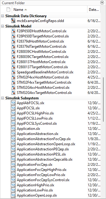
If you modify an existing base hardware model (for changes in processor architecture, inverter, and motor), ensure that you replicate these changes in the example working directory.
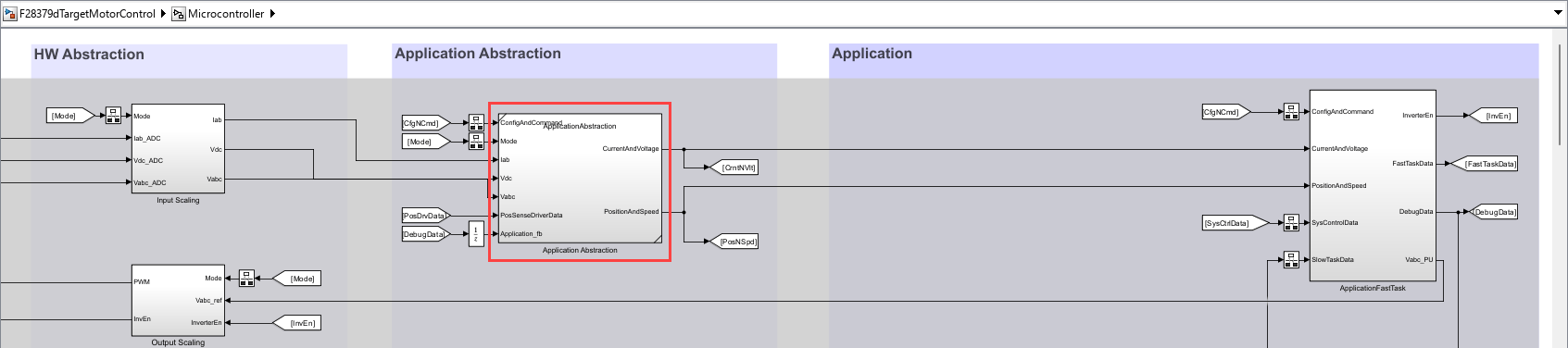
When creating or modifying a base hardware model, ensure that you do not change the pre-existing subsystem references in the base hardware model.
When creating or modifying a base hardware model, ensure that you do not change the signal connections between the subsystems present in the base hardware model and the subsystem references.
For example, because the
Application Abstractionsubsystem in the base hardware modelF28379dTargetMotorControl.slxis a subsystem reference, ensure that you do not change the following connections:Connections between
Application AbstractionandApplicationFastTasksubsystems.Connections between
Application AbstractionandInput Scalingsubsystems.
If you are create a new base model hardware, use the procedure described in the Modify Processor section to add the new hardware target to the reference example live script (using the
mcbAddHardwareToListfunction).Use the HardwareTarget field in the reference example live script to select the newly added or the modified hardware target.
Use the ControlAlgorithm field in the reference example live script to select any control algorithm.
Run the
mcbOpenExamplefunction to generate and open the target and host models for the newly added or the modified hardware target and the selected control algorithm. For details about running the function, see the Find and Open Models section of the example live script.Therefore, you can use any control algorithm with the newly added or the modified hardware target to generate the target and host models for your motor control application.
Workflow 2: Modify Control Algorithm
This workflow explains the procedure to add a new control algorithm to the Generate Motor Control Models for Selected Algorithm and Hardware reference example by modifying an existing algorithm. You can use a similar workflow to update the control algorithm that a Simulink-based motor control implementation uses.
The reference example supports the different control algorithms (such as
Open Loop V/F and FOC QEP
that you can select using the ControlAlgorithm field in the
reference example live script). For more details, see Select Control Algorithm section of the example live script.
Follow this procedure to add a new control algorithm (by modifying an existing algorithm) and use the newly added algorithm with a base hardware model.
Navigate to the working directory for the Generate Motor Control Models for Selected Algorithm and Hardware reference example.
The following image shows the example working directory.
Use the Select Control Algorithm section of the Generate Motor Control Models for Selected Algorithm and Hardware reference example live script to select an existing control algorithm that closely matches the algorithm that you want to implement. For example, you can select the
FOC
            QEP
control algorithm if you want implement a field-oriented control (FOC)-based algorithm.Use the Select Hardware section of the reference example live script to select a hardware that you want to use.
Run the
mcbOpenExamplefunction to create a directorytemp(inside the example working directory) with the following files (running the function also opens the target and host models for the selected control algorithm and hardware target):Copy of all the Simulink subsystem files associated with the control algorithm you selected.
Target and host models that the example generated.
Initialization scripts for the generated models.
For details about running the function, see the Find and Open Models section of the example live script.
Navigate to the
tempdirectory. Modify the algorithm in the relevant subsystem files according to the new control algorithm that you want to implement.Ensure that you do not change the signal connections between the subsystems present in the base hardware model and the subsystem references.
For example, because the
Application Abstractionsubsystem in the base hardware modelF28379dTargetMotorControl.slxis a subsystem reference, ensure that you do not change the following connections:Connections between
Application AbstractionandApplicationFastTasksubsystems.Connections between
Application AbstractionandInput Scalingsubsystems.
Rename the modified subsystem files appropriately.
Copy the modified subsystem files to the example working directory. Proceed to step 9 to add the new control algorithm (that you implemented using steps 5 to 8) to the ControlAlgorithm field in the reference example live script.
Use the MATLAB command prompt to run the
mcbAddAlgorithmToListfunction by using the subsystem files (or Simulink subsystem references associated with the new control algorithm) as arguments. For details about running this function, see Add Algorithm Reference to List section of the example live script.After you run the
mcbAddAlgorithmToListfunction, the ControlAlgorithm field in the live script shows the new control algorithm that you implemented. Select the newly added control algorithm.Use the HardwareTarget field in the reference example live script to select any hardware target.
Run the
mcbOpenExamplefunction to generate and open the target and host models for the newly added control algorithm and the selected hardware target.Therefore, you can use any hardware target with the new control algorithm to generate the target and host models for your motor control application.
See Also
Topics
- Generate Motor Control Models for Selected Algorithm and Hardware
- Run 3-Phase AC Motors in Open-Loop Control and Calibrate ADC Offset
- Quadrature Encoder Offset Calibration for PMSM
- Estimate PMSM Parameters Using Parameter Estimation Blocks
- Estimate PMSM Parameters Using Parameter Estimation Blocks on Real-Time Systems
- Field-Oriented Control of PMSM Using Quadrature Encoder
- Sensorless Field-Oriented Control of PMSM
- Open-Loop and Closed-Loop Motor Control Techniques
- Host-Target Communication
- Current Sensor ADC Offset and Position Sensor Calibration
- Field-Oriented Control