How to Tune Sensorless Position Estimators
This topic shows you how to tune sensorless position estimators such as extended EMF observer and sliding mode observer such that they compute mechanical rotor position accurately.
An FOC algorithm requires real-time rotor position feedback to implement speed control as well as to perform mathematical transformation on the reference stator voltages and feedback currents. Traditionally, such algorithms rely on physical sensors. However, due to increased accuracy and cost effectiveness, sensorless position estimation solutions can act as a better alternative to physical sensors.
The Extended EMF Observer block from Motor Control Blockset™ computes the electrical position, in addition to the mechanical speed of the PMSM from the measured voltage and current in the stationary αβ reference frame. For more details about this block, see Extended EMF Observer.
The Sliding Mode Observer block from Motor Control Blockset computes the electrical position and mechanical speed of a surface mount PMSM by using the voltage and current values along the α- and β-axes of the stationary αβ reference frame. For more details about this block, see Sliding Mode Observer.
These sensorless estimators need tuning to ensure that they estimate rotor position accurately. This topic explains the workflow to tune the Extended EMF Observer and Sliding Mode Observer sensorless estimators.
Tuning Extended EMF Observer
After you implement a closed-loop motor control algorithm, such as field-oriented control (FOC), that uses the Extended EMF Observer block to compute the real-time rotor position using sensorless position estimation algorithm, use this workflow to tune the extended EMF observer.
This workflow uses the Simulink® model mcb_pmsm_foc_sensorless_f28379d to demonstrate
the tuning procedure. You can use a similar procedure to tune the extended EMF observer
available inside your motor control algorithm.
Pre-requisites
Obtain the motor parameters. The Simulink model contains the default motor parameters that you can replace with the values from either the motor datasheet or other sources.
However, if you have the motor control hardware, you can estimate the parameters for the motor that you want to use, by using the Motor Control Blockset parameter estimation tool. For instructions , see Estimate PMSM Parameters Using Parameter Estimation Blocks.
The parameter estimation tool updates the motorParam variable (in the MATLAB® workspace) with the estimated motor parameters.
If you obtain the motor parameters from the datasheet or other sources, update the motor parameters and inverter parameters in the model initialization script
mcb_pmsm_foc_sensorless_f28379d_datascriptassociated with the Simulink model. The motor block available inside the Simulink model obtains the motor parameters from this script.If you use the parameter estimation tool, you can update the inverter parameters, but do not update the motor parameters in the model initialization script. The script automatically extracts motor parameters from the updated motorParam workspace variable.
Procedure to Tune Extended EMF Observer
Use the following procedure to tune the sensorless Extended EMF Observer block.
Open the model
mcb_pmsm_foc_sensorless_f28379d.slx.Click Run on the Simulation tab to simulate the model.
Run the motor using open-loop control by setting the reference speed to 10% of rated motor speed.
To set this reference speed value, set the variable Speed_openLoop_PU available in the model initialization script to 0.1 per-unit (PU).
Click Data Inspector on the Simulation tab to observe the simulation results. Click the Stop button to stop the simulation after sometime.
Ensure that the motor block (Surface Mount PMSM available inside the subsystem
mcb_pmsm_foc_sensorless_f28379d/Inverter and
                        Motor - Plant Model/Simulation
) obtains the correct motor parameters by updating them in the model initialization scriptmcb_pmsm_foc_sensorless_f28379d_datascript.m.Use the EEMF filter cutoff frequency (Hz) parameter available in the Observer Parameters tab of the Extended EMF Observer block parameters dialog box to set the cutoff frequency of the extended EMF observer to 10 times the maximum electrical frequency of motor operation.
Use the default state observer gain (EEMF observer gain parameter available in the Observer Parameters tab) to simulate the model. Verify if the feedback speed matches the reference speed.
If the feedback speed does not match the reference speed (actual and estimated position does not match), set the EEMF observer gain parameter to a very low value (for example,
0.001) and simulate the model again to run the motor using open-loop control. Verify if the feedback speed matches the reference speed and that the motor electrical position matches the position estimated by the observer.The following image shows an example of the reference and feedback speeds along with the actual and estimated electrical position that the model generates using an state observer gain of
0.001.
If the feedback speed does not match the reference speed (actual and estimated position does not match), set the EEMF observer gain parameter to a higher value (for example,
0.001*10) and simulate the model again to run the motor using open-loop control. Verify if the feedback speed matches the reference speed and that the motor electrical position matches the position estimated by the observer.The following image shows an example of the reference and feedback speeds along with the actual and estimated electrical position that the model generates using an state observer gain of
0.001*10.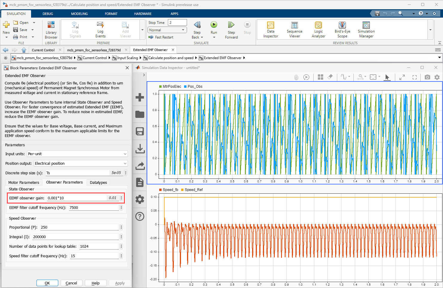
Repeat step-9 (multiply state observer gain by 10, simulate the model, and observe the simulation results again) until the feedback speed matches reference speed (observer position matches the actual rotor electrical position) as shown in the following figures.
The following image shows an example of the reference and feedback speeds along with the actual and estimated electrical position that the model generates using an state observer gain of
0.001*100.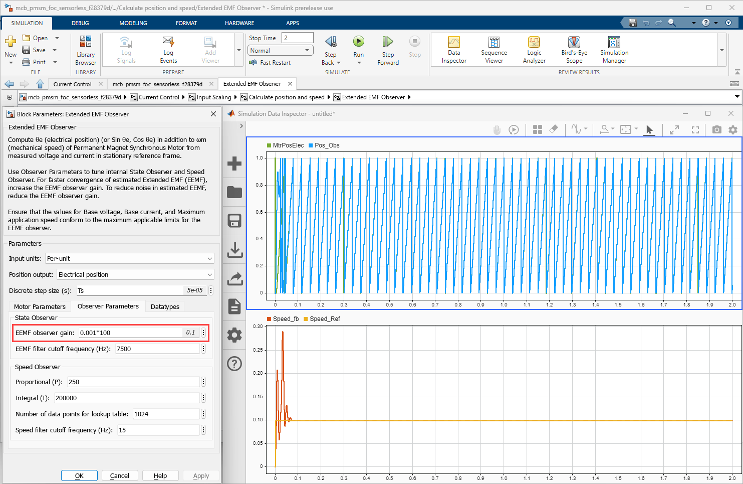
The following image shows an example of the reference and feedback speeds along with the actual and estimated electrical position that the model generates using an state observer gain of
0.001*10000. In this case, the reference and feedback speeds (actual and estimated electrical positions) match as shown in the following figure.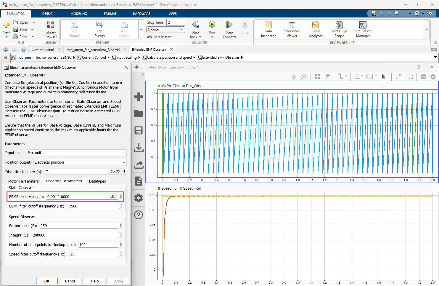
Retain the state observer gain that you finalized in step 10 (for example,
0.001*10000) but increase the ratio Kp/Ki (and then simulate the model to run the motor using open-loop control) until the feedback speed shows sufficient damping.Use the Proportional (P) parameter to gradually increase the speed observer gain Kp as shown in the following figures.
The following image shows damping in the feedback speed signal when the Kp gain value is
250/1000.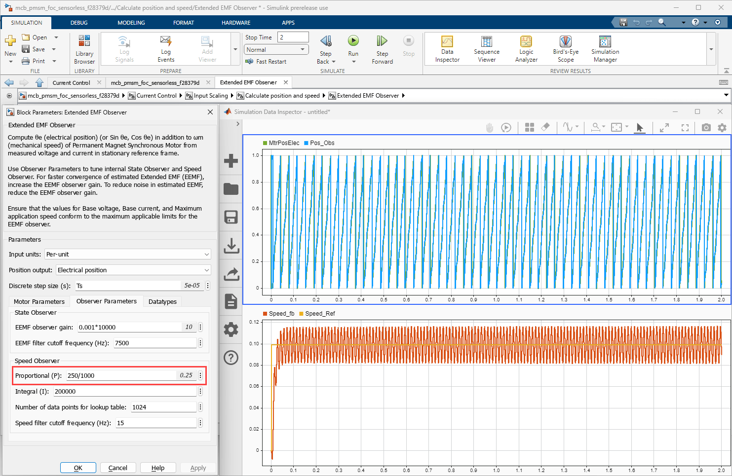
The following image shows increased damping in the feedback speed signal when the Kp gain value is
250/10.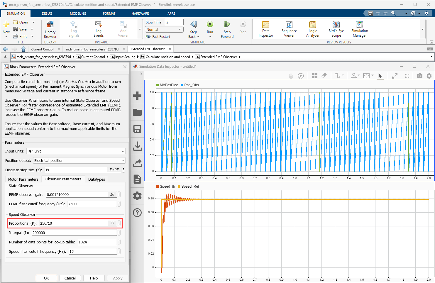
After you finalize the speed observer gain (Kp), fine tune the state and speed observer gains (using the EEMF observer gain and Proportional (P) parameters) to improve position and speed tracking performance of the Extended EMF Observer block.
Note
Before you increase the reference speed (Speed_openLoop_PU) and switch to closed-loop control, ensure that the extended EMF observer tracks the rotor electrical position accurately.
Tuning Sliding Mode Observer
After you implement a closed-loop motor control algorithm, such as field-oriented control (FOC), that uses the Sliding Mode Observer block to compute the real-time rotor position using sensorless position estimation algorithm, you must tune the sliding mode observer.
For instructions to tune the sliding mode observer, see Tuning Sliding Mode Observer.
See Also
Extended EMF Observer | Sliding Mode Observer | Flux Observer | Pulsating High Freq Observer