I-F Controller
Implement I-F control for a three-phase permanent magnet synchronous motor
Since R2024a
Libraries:
Motor Control Blockset /
Controls /
Controllers
Description
The I-F Controller block implements I-F control based sensorless startup algorithm for a three-phase permanent magnet synchronous motor (PMSM).
Similar to the VbyF Controller block, the I-F Controller block enables sensorless motor startup, however, I-F Controller generates a higher startup torque in the motor.
The block computes the d- and q-axis reference currents along with reference electrical position for the PMSM. It accepts electrical position, q-axis current, as well as reference and actual mechanical speeds as inputs.
The block supports both the SI unit and per-unit (PU) systems. For more information about the per-unit system, see Per-Unit System.
In addition, you can use the advanced options to enable the ParameterBus input port, which you can use with the Compute Parameter block to update the block parameters optimally at run-time. You can use this functionality when motor parameters can change over time, for example, while building applications that may require swapping of motors at run-time.
For information about the block algorithm, see Algorithm.
Examples
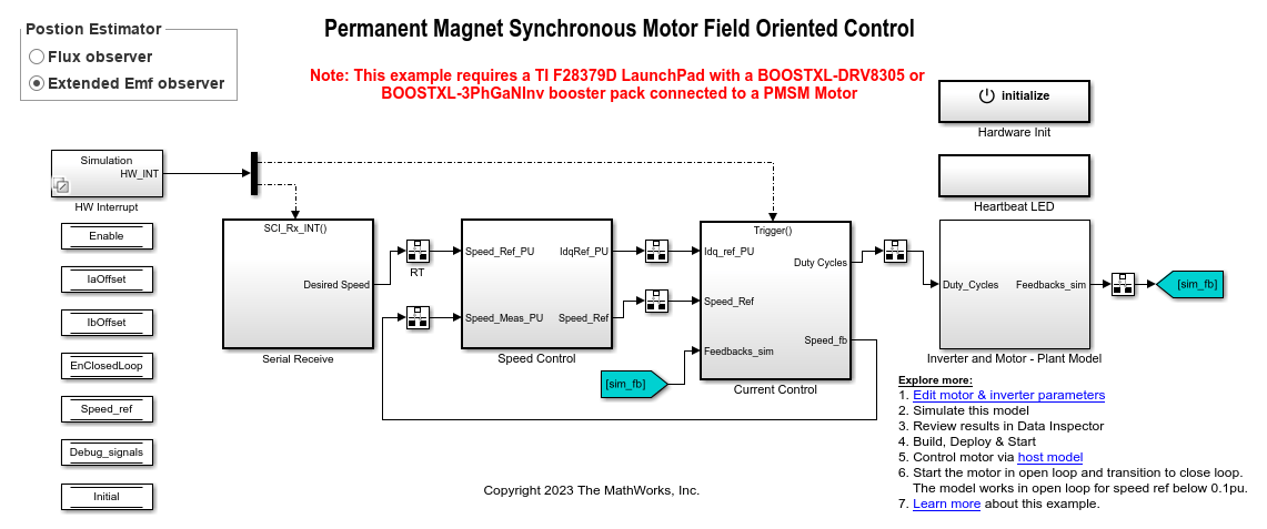
Sensorless Field-Oriented Control of PMSM Using I-F Control-Based Startup
Implements field-oriented control (FOC) using sensorless position estimation and I-F control-based startup to control the speed of a three-phase permanent magnet synchronous motor (PMSM).
Ports
Input
Enable — Option to enable block algorithm
scalar
Signal that enables block algorithm:
1
— Enables block algorithm.0
— Reset block algorithm.
Data Types: single
| double
| fixed point
θe — Electrical position of motor
scalar
The electrical position of the rotor.
Data Types: single
| double
| fixed point
ωm ref
— Reference motor mechanical speed
scalar
Reference mechanical speed for running the motor using I-F control.
Data Types: single
| double
| fixed point
ωm — Motor mechanical speed
scalar
Actual mechanical speed of the motor.
Data Types: single
| double
| fixed point
Iq — Q-axis stator current
scalar
Stator current along the q-axis of the rotating dq reference frame..
Data Types: single
| double
| fixed point
Vq — Q-axis stator voltage
scalar
Stator voltage along the q-axis of the rotating dq reference frame..
Data Types: single
| double
| fixed point
ParameterBus — Computed parameters for I-F controller
bus
Computed parameters for the I-F Controller block. The input port accepts the following parameters:
Number of pole pairs
Speed to exit I-F controller (RPM), ω1
Speed to re-enter I-F controller (RPM), ω2
Maximum current (A), Imax
Maximum rate of speed change (RPM/s)
Maximum current decay rate (A/s)
Idle time (s)
Damping coefficient, ζ
Use this port along with the Compute Parameter block to update the preceding block parameters optimally at run-time.
Dependencies
To enable this port, select the Use input port for computed parameters (run-time motor swap) parameter available in the Advanced Options section.
Data Types: single
| double
Output
Idref
— Reference d-axis current
scalar
Reference d-axis stator current leading to currents that drive the motor.
Data Types: single
| double
| fixed point
Iqref — Reference q-axis current
scalar
Reference q-axis stator current leading to currents that drive the motor.
Data Types: single
| double
| fixed point
θeref — Generated reference electrical position of motor
scalar
Reference electrical position of motor generated by the block that drives the motor.
Data Types: single
| double
| fixed point
Status — I-F control status
scalar
Status of the I-F control algorithm.
1
— Indicates that I-F control is inactive.0
— Indicates that I-F control is active.
Data Types: single
| double
| fixed point
Parameters
Enable speed damping — Option to enable block to apply speed oscillation damping compensation
off
(default) | on
Select this parameter to apply speed oscillation damping to the motor electrical speed (according to assumed motor position) with speed oscillations.
Use input port for computed parameters (run-time motor swap) — Option to enable input port to accept computed parameters
off
(default) | on
Select this parameter to enable the ParameterBus input port and disable the following parameters:
Number of pole pairs
Current unit
Base current (A)
Speed to exit I-F controller (RPM), ω1
Speed to re-enter I-F controller (RPM), ω2
Maximum current (A), Imax
Maximum rate of speed change (RPM/s)
Maximum current decay rate (A/s)
Idle time (s)
Voltage unit
Base voltage (V)
Damping coefficient, ζ
This parameter enables you to use the input port along with the Compute Parameter block to update block parameters optimally at run-time.
Number of pole pairs — Number of pole pairs available in motor
4
(default) | scalar
Number of pole pairs available in the motor.
Dependencies
To enable this parameter, clear the Use input port for computed parameters (run-time motor swap) parameter available in the Advanced Options section.
Position unit — Unit of electrical position
Degrees
(default) | Radians
| Per-unit
Unit of θe input and θeref output used by the block.
Select Per-unit
to use per-unit system for the
reference electrical position input and output. For more information about the
per-unit system, see Per-Unit System.
Speed unit — Unit of the speed inputs
Degrees/Sec
(default) |
Radians/Sec
|
RPM
|
Per-unit
Units of the ωmref and ωm inputs.
Select Per-unit
to use per-unit system for the two
speed inputs. For more information about the per-unit system, see Per-Unit System.
Per unit speed (RPM) — Speed corresponding to one per-unit
6000
(default) | scalar
Speed value corresponding to one per-unit. For details, see Per-Unit System.
Dependencies
To enable this parameter, set Speed unit to
Per-unit
.
Current unit — Unit of motor currents
SI unit
(default) | Per-unit
Unit of Iq input as well as Idref and Iqref outputs of the block.
Select Per-unit
to use per-unit system for these
motor currents. For more information about the per-unit system, see Per-Unit System.
Dependencies
To enable this parameter, clear the Use input port for computed parameters (run-time motor swap) parameter available in the Advanced Options section.
Base current (A) — Nominal current corresponding to one per-unit
21.4286
(default) | scalar
Nominal current value corresponding to one per-unit. For details, see Per-Unit System.
Dependencies
To enable this parameter:
Clear the Use input port for computed parameters (run-time motor swap) parameter available in the Advanced Options section.
Set Current unit to
Per-unit
.
Discrete step size (s) — Interval between consecutive block executions
50e-6
(default) | scalar
The fixed time interval in seconds between two consecutive instances of block execution.
Controller Parameters
Speed to exit I-F controller (RPM), ω1 — Speed (after motor starts) at which I-F control stops
410.7
(default) | scalar
Speed (after motor starts) until which the I-F controller remains active (in RPM). When the motor speed exceeds this value, the I-F controller becomes inactive and the Status block output turns true.
Dependencies
To enable this parameter, clear the Use input port for computed parameters (run-time motor swap) parameter available in the Advanced Options section.
Speed to re-enter I-F controller (RPM), ω2 — Speed required to re-enter I-F control
287.49
(default) | scalar
After exiting I-F control (and entering closed-loop control), speed required to reactivate the I-F controller (in RPM). When the motor speed falls below this value, the I-F controller becomes active again and the Status block output turns false.
Dependencies
To enable this parameter, clear the Use input port for computed parameters (run-time motor swap) parameter available in the Advanced Options section.
Maximum current (A), Imax — Maximum motor current during I-F control
6.39
(default) | scalar
Maximum current (in amperes) that is supplied to the motor when I-F control is active.
Dependencies
To enable this parameter, clear the Use input port for computed parameters (run-time motor swap) parameter available in the Advanced Options section.
Maximum rate of speed change (RPM/s) — Maximum rate of speed change during I-F control
960
(default) | scalar
Maximum rate at which motor speed can change (in RPM/s) when I-F control is active.
Dependencies
To enable this parameter, clear the Use input port for computed parameters (run-time motor swap) parameter available in the Advanced Options section.
Maximum current decay rate (A/s) — Maximum rate of current decay during I-F control
111.8250
(default) | scalar
Maximum rate at which motor current can decay (in amperes/s) when I-F control is active.
Dependencies
To enable this parameter, clear the Use input port for computed parameters (run-time motor swap) parameter available in the Advanced Options section.
Idle time (s) — Time of constant speed and current
1
(default) | scalar
Time (in seconds) during which both motor speed and current remains constant when I-F control is active.
Dependencies
To enable this parameter, clear the Use input port for computed parameters (run-time motor swap) parameter available in the Advanced Options section.
Minimum allowed position error for transition (rad) — Threshold error for closed-loop transition
0.1745
(default) | scalar
Threshold electrical position error (between θe and θeref ) below which the block transitions from I-F control to closed-loop control.
Advanced Parameters
To enable this tab, select the Enable speed damping parameter.
Voltage unit — Unit of stator voltages
SI unit
(default) | Per-unit
Unit of Vα and Vβ stator voltages.
Select Per-unit
to use per-unit system for these
voltages. For more information about the per-unit system, see Per-Unit System.
Dependencies
To enable this parameter:
Select the Enable speed damping parameter.
Clear the Use input port for computed parameters (run-time motor swap) parameter available in the Advanced Options section.
Base voltage (V) — Nominal voltage corresponding to one per-unit
13.8564
(default) | scalar
Nominal voltage value corresponding to one per-unit. For details about the per-unit system, see Per-Unit System.
Dependencies
To enable this parameter:
Select the Enable speed damping parameter.
Clear the Use input port for computed parameters (run-time motor swap) parameter available in the Advanced Options section.
Set Voltage unit to
Per-unit
.
Damping coefficient, ζ — Speed oscillation damping coefficient value
2.6172
(default) | scalar
Value of the speed oscillation damping coefficient (K) that the block should use.
Dependencies
To enable this parameter:
Select the Enable speed damping parameter.
Clear the Use input port for computed parameters (run-time motor swap) parameter available in the Advanced Options section.
Algorithms
The following equations explain the I-F control algorithm used by the block for a PMSM.
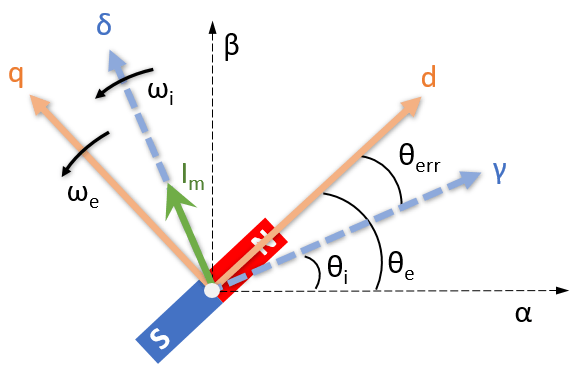
The preceding figure explains the I-F control operation. It shows the γ-ẟ rotating orthogonal axes (aligned with assumed rotor position), the d-q axes in the rotating reference frame, and the stationary α-β reference frame.
The following equation describes the electrical torque of PMSM when I-F control is active:
The mechanical equation of PMSM is
During steady state operation:
The following equation describes the relationship between θerr and Im:
where:
Te is the electromagnetic torque of the motor (in Nm).
Tl is the load torque of the motor (in Nm).
p is the number of pole pairs of the motor.
λpm is the permanent magnet flux linkage (in Weber).
id is the motor current along the d-axis of the d-q rotating reference frame (in amperes).
iq is the motor current along the q-axis of the d-q rotating reference frame (in amperes).
Ld is the d-axis inductance of the motor (in henries).
Lq is the q-axis inductance of the motor (in henries).
Im is the current injected by the I-F control algorithm (in amperes).
θe is the actual rotor position (in radians).
θi is the assumed (reference) rotor position (in radians).
θerr is the difference between the actual and assumed rotor position (in radians).
ωe is the electrical speed of the motor (in rad/s).
J is the motor inertia (in kgm^2)
B is the friction constant (in Nms).
When using this algorithm, the magnitude of the starting current determines the maximum electrical torque that the I-F control algorithm can generate.
The preceding equations also show that a very high acceleration value can affect the stability of I-F control. The error between actual and assumed motor position depends on the magnitude of the supplied current.
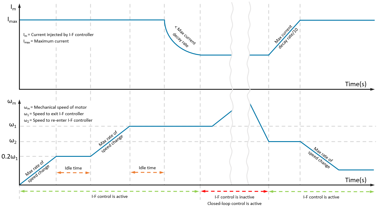
The following image shows the operation of the I-F control, which begins with motor-start followed by transition from I-F to closed-loop control and from closed-loop to I-F control.
The I-F control algorithm provides good control over torque during motor startup. The control algorithm starts the motor without any current overshoots as well as provides a smooth I-F control to closed-loop control transition.
Speed Oscillation Damping
The mechanical damping offered by the motor is not sufficient to reduce the oscillations in the motor speed. Compensating for these oscillations requires addition of negative feedback in the speed generation algorithm, which increases the damping coefficient (K).
This equation describes the compensated motor speed that the block generates (where KΔP is the applied compensation for speed oscillation damping).
where:
ωi is the reference motor electrical speed after compensation (in rad/s).
ωi* is the reference motor electrical speed with speed oscillations (in rad/s).
θi is the reference rotor position (in radians).
K is the damping coefficient.
P is the active power drawn by the motor (in watts).
Vq is the stator voltage along the q-axis of the rotating dq reference frame.
Iq is the stator current along the q-axis of the rotating dq reference frame.
References
[1] Z. Wang, K. Lu and F. Blaabjerg, "A Simple Startup Strategy Based on Current Regulation for Back-EMF-Based Sensorless Control of PMSM," in IEEE Transactions on Power Electronics, vol. 27, no. 8, pp. 3817-3825, Aug. 2012, doi: 10.1109/TPEL.2012.2186464.
[2] A. Borisavljevic, H. Polinder and J. A. Ferreira, "Realization of the I/f control method for a high-speed permanent magnet motor," The XIX International Conference on Electrical Machines - ICEM 2010, Rome, Italy, 2010, pp. 1-6, doi: 10.1109/ICELMACH.2010.5607892.
[3] S. V. Nair, K. Hatua, N. V. P. R. D. Prasad and D. K. Reddy, "A Quick I--f Starting of PMSM Drive With Pole Slipping Prevention and Reduced Speed Oscillations," in IEEE Transactions on Industrial Electronics, vol. 68, no. 8, pp. 6650-6661, Aug. 2021, doi: 10.1109/TIE.2020.3005070.
[4] Z. Song, W. Yao, K. Lee and W. Li, "An Efficient and Robust I-f Control of Sensorless IPMSM With Large Startup Torque Based on Current Vector Angle Controller," in IEEE Transactions on Power Electronics, vol. 37, no. 12, pp. 15308-15321, Dec. 2022, doi: 10.1109/TPEL.2022.3193565.
Extended Capabilities
C/C++ Code Generation
Generate C and C++ code using Simulink® Coder™.
Fixed-Point Conversion
Design and simulate fixed-point systems using Fixed-Point Designer™.
Version History
Introduced in R2024a
MATLAB Command
You clicked a link that corresponds to this MATLAB command:
Run the command by entering it in the MATLAB Command Window. Web browsers do not support MATLAB commands.
Select a Web Site
Choose a web site to get translated content where available and see local events and offers. Based on your location, we recommend that you select: .
You can also select a web site from the following list
How to Get Best Site Performance
Select the China site (in Chinese or English) for best site performance. Other MathWorks country sites are not optimized for visits from your location.
Americas
- América Latina (Español)
- Canada (English)
- United States (English)
Europe
- Belgium (English)
- Denmark (English)
- Deutschland (Deutsch)
- España (Español)
- Finland (English)
- France (Français)
- Ireland (English)
- Italia (Italiano)
- Luxembourg (English)
- Netherlands (English)
- Norway (English)
- Österreich (Deutsch)
- Portugal (English)
- Sweden (English)
- Switzerland
- United Kingdom (English)
Asia Pacific
- Australia (English)
- India (English)
- New Zealand (English)
- 中国
- 日本Japanese (日本語)
- 한국Korean (한국어)