Main Content

phased.NRAntennaElement

5G antenna element described in 3GPP TR 38.901 specification

Since R2021a

Description

The NRAntennaElement System object™ models an antenna designed to meet the 3GPP TR 38.901 standard [1].

To compute the response of the antenna element for specified directions:

  1. Create the phased.NRAntennaElement object and set its properties.

  2. Call the object with arguments, as if it were a function.

To learn more about how System objects work, see What Are System Objects?

Creation

Description

example

antenna = phased.NRAntennaElement creates an NR antenna System object, antenna, that follows the standard specified in 3GPP TR 38.901 [1].

example

antenna = phased.NRAntennaElement(Name,Value) creates an NR antenna element object, antenna, and sets each specified property set to the specified value. You can specify additional name-value pair arguments in any order as (Name1,Value1,...,NameN,ValueN).

Properties

expand all

Unless otherwise indicated, properties are nontunable, which means you cannot change their values after calling the object. Objects lock when you call them, and the release function unlocks them.

If a property is tunable, you can change its value at any time.

For more information on changing property values, see System Design in MATLAB Using System Objects.

Operating frequency range of the antenna, specified as a nonnegative, real-valued, 1-by-2 row vector in the form [LowerBound HigherBound]. The antenna element has no response outside the specified frequency range. Units are in Hz.

Data Types: double

Polarization slant angle of the antenna, specified as a scalar. The polarization slant angle is defined in section 7.3.2 of the 3GPP TR 38.901 Release 14 [1]. Units are in degrees.

Example: 45.0

Data Types: double

Polarization model, specified as either 1 or 2. The polarization models are defined in section 7.3.2 of the 3GPP TR 38.901 Release 14 [1].

Example: 1

Data Types: double

Beamwidth of the antenna pattern, specified as either a scalar or a 1-by-2 real-valued vector. When the specified value is a 1-by-2 vector, it has the form of [AzimuthBeamwidth ElevationBeamwidth]. If the specified value is a scalar, the azimuth and elevation beamwidths are equal. Units are in degrees.

Example: 40

Data Types: double

Attenuation of maximum sidelobe level of the antenna pattern, specified as either a positive scalar or a 1-by-2 real-valued vector of positive numbers. When the specified value is a 1-by-2 vector, it has the form of [AzimuthSidelobe ElevationSidelobe]. If the specified value is a scalar, the azimuth and elevation sidelobe levels are equal. Units are in dB.

Example: 24

Data Types: double

Maximum attenuation to the main lobe in the antenna pattern specified as a positive scalar. This value should be no less than the values specified in the SidelobeLevel property. Units are in dB.

Example: 28

Data Types: double

Maximum gain of the main lobe in the antenna pattern specified as a positive scalar. Units are in dB.

Example: 5

Data Types: double

Usage

Description

example

RESP = antenna(FREQ,ANG) returns the antenna voltage response RESP at the operating frequencies specified in FREQ and directions specified in ANG.

Note

The object performs an initialization the first time the object is executed. This initialization locks nontunable properties and input specifications, such as dimensions, complexity, and data type of the input data. If you change a nontunable property or an input specification, the System object issues an error. To change nontunable properties or inputs, you must first call the release method to unlock the object.

Input Arguments

expand all

Operating frequency of the antenna element, specified as a nonnegative scalar or nonnegative, real-valued 1-by-L row vector. Frequency units are in Hz.

FREQ must lie within the range of values specified by the FrequencyRange or the FrequencyVector property of the element. Otherwise, the element produces no response and the response is returned as –Inf. Element objects use the FrequencyRange property, except for phased.CustomAntennaElement, which uses the FrequencyVector property.

Example: [1e8 2e6]

Data Types: double

Azimuth and elevation angles of the response directions, specified as a real-valued 1-by-M row vector or a real-valued 2-by-M matrix, where M is the number of angular directions. Angle units are in degrees. The azimuth angle must lie in the range –180° to 180°, inclusive. The elevation angle must lie in the range –90° to 90°, inclusive.

  • If ANG is a 1-by-M vector, each element specifies the azimuth angle of the direction. In this case, the corresponding elevation angle is assumed to be zero.

  • If ANG is a 2-by-M matrix, each column of the matrix specifies the direction in the form [azimuth;elevation].

The azimuth angle is the angle between the x-axis and the projection of the direction vector onto the xy-plane. This angle is positive when measured from the x-axis toward the y-axis. The elevation angle is the angle between the direction vector and xy-plane. This angle is positive when measured toward the z-axis. See the definition of Azimuth and Elevation Angles.

Example: [110 125; 15 10]

Data Types: double

Output Arguments

expand all

Voltage response of the antenna element, returned as a complex-valued M-by-L matrix. In this matrix, M represents the number of angles specified in ANG and L represents the number of frequencies specified in FREQ.

Data Types: double

Object Functions

To use an object function, specify the System object as the first input argument. For example, to release system resources of a System object named obj, use this syntax:

release(obj)

expand all

beamwidthCompute and display beamwidth of sensor element pattern
directivityDirectivity of antenna or transducer element
isPolarizationCapableAntenna element polarization capability
patternPlot antenna or transducer element directivity and patterns
patternAzimuthPlot antenna or transducer element directivity and pattern versus azimuth
patternElevationPlot antenna or transducer element directivity and pattern versus elevation
stepRun System object algorithm
releaseRelease resources and allow changes to System object property values and input characteristics
resetReset internal states of System object

Examples

collapse all

Construct an antenna based on the 3GPP 38.901 standard and plot its elevation response at 6 MHz.

antenna = phased.NRAntennaElement;
fc = 6e9;
pattern(antenna,fc,-180:180,0,'CoordinateSystem','polar');

Find the response of the antenna at the boresight.

ang = [0;0];
resp = antenna(fc,ang)
resp = struct with fields:
    H: 0
    V: -2.5119

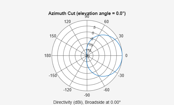
Construct an NR antenna based on the 3GPP 38.901 standard with its Polarization Model set to "1". Then, find its response at boresight. Finally, plot its antenna response as a function of azimuth angle at 6 GHz.

    element = phased.NRAntennaElement('PolarizationModel',1);
    fc = 6e9;
    ang = [0;0];
    resp = element(fc,ang)
resp = struct with fields:
    H: 0
    V: -2.5119

Plot the antenna pattern at 0 degrees elevation for all azimuth angles.

    pattern(element,fc,-180:180,0,'CoordinateSystem','polar') 

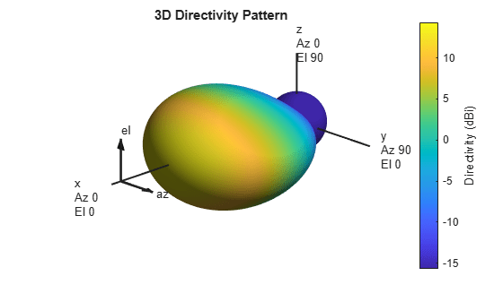
Construct an NR antenna based on the 3GPP 38.901 standard. Set the antenna beamwidth to 45 degrees in azimuth and 30 degrees in elevation. Find the antenna response at boresight. Then, plot the antenna response as a function of azimuth and elevation at 6 GHz.

    element = phased.NRAntennaElement('Beamwidth',[45,30]);
    fc = 6.0e9;
    ang = [0;0];
    resp = element(fc,ang)
resp = struct with fields:
    H: 0
    V: -2.5119

Plot the 3D antenna pattern for all azimuth angles and elevation angles.

    pattern(element,fc,-180:180,-90:90,'CoordinateSystem','polar') 

References

[1] 5G: Study on channel model for frequencies from 0.5 to 100 GHz, 3GPP TR38.901 Version 14.0.0 Release 14.

Extended Capabilities

Version History

Introduced in R2021a