landSurface
Description
LandSurface defines a land surface object belonging to a radarScenario.
Manage surfaces in a radar scenario using SurfaceManager.
Surface reflectivity, or normalized radar cross section, is defined as a surfaceReflectivityLand or surfaceReflectivityCustom
System object™.
You can use landSurface function to specify surface extent,
reflectivity, reference height, and digital elevation terrain data. Use the occlusion object
function to test for occlusion along the line-of-sight between two points in the scenario and
use height to provide
surface height at a point.
Creation
Description
srf = landSurface(scenario)LandSurface object, srf, to the radar
scenario radarScenario
object scenario.
srf = landSurface(scenario,PropertyName=Value)LandSurface object, srf, with each specified
PropertyName set to the corresponding Value.
You can specify additional pairs of arguments in any order as
PropertyName1=Value1,...,PropertyNameN=ValueN.
Properties
Object Functions
height | Height of point on surface |
occlusion | Test for occlusion of point by a surface |
plotReflectivityMap | Plots reflectivity map |
Examples
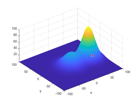
Create a surface with two hills. Plot the surface on a 200-by-200 meter grid with grid points one meter apart. Add the surface to a radar scenario. Assume the surface has a radar reflectivity defined by a constant gamma model.
[x,y] = meshgrid(linspace(-100,100,201));
ht1 = 40*exp(-(x.^2 + y.^2)/30^2);
ht2 = 100*exp(-((x-60).^2 + y.^2)/25^2);
ht = ht1 + ht2;
p = surfc(x(1,:),y(:,1),ht);
axis equal
axis tight
shading interp
simTime = 3;
scene = radarScenario(UpdateRate = 1, ...
    IsEarthCentered = false,StopTime = simTime);
gammaDB = surfacegamma('Flatland');
refl = surfaceReflectivityLand(Model = 'ConstantGamma',Gamma = gammaDB);
srf = landSurface(scene,RadarReflectivity = refl, ...
    Terrain = ht,Boundary = [-100,100;-100,100]);
Use surface manager to identify the surface.
scene.SurfaceManager
ans =
  SurfaceManager with properties:

    EnableMultipath: 0
       UseOcclusion: 1
           Surfaces: [1×1 radar.scenario.LandSurface]
scene.SurfaceManager.Surfaces
ans =
  LandSurface with properties:

        RadarReflectivity: [1×1 surfaceReflectivityLand]
    ReflectionCoefficient: [1×1 radar.scenario.SurfaceReflectionCoefficient]
          ReflectivityMap: 1
          ReferenceHeight: 0
                 Boundary: [2×2 double]
                  Terrain: [201×201 double]
Obtain and plot the height of the surface at the point (50,-30).
xt = 50;
yt = -30;
htx = height(srf,[xt,yt])
htx =
21.1046
hold on
plot3(xt,yt,htx+5,'ow','MarkerFaceColor','r')
xlabel('x')
ylabel('y')
hold off
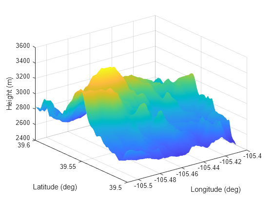
Create a radar scenario and specify its IsEarthCentered property as true to use DTED file.
scene = radarScenario(IsEarthCentered = true);
Model the reflectivity as a constant gamma surface.
refl = surfaceReflectivityLand(Model = 'ConstantGamma',Gamma = -20);Add a 0.1-by-0.1 degree land surface derived from a DTED file.
bdry = [39.5 39.6;-105.51 -105.41];
srf = landSurface(scene,Terrain = 'n39_w106_3arc_v2.dt1', ...
    Boundary = bdry,RadarReflectivity = refl)
srf =
  LandSurface with properties:

        RadarReflectivity: [1×1 surfaceReflectivityLand]
    ReflectionCoefficient: [1×1 radar.scenario.SurfaceReflectionCoefficient]
          ReflectivityMap: 1
          ReferenceHeight: 0
                 Boundary: [2×2 double]
                  Terrain: 'n39_w106_3arc_v2.dt1'
mgr = scene.SurfaceManager
mgr =
  SurfaceManager with properties:

    EnableMultipath: 0
       UseOcclusion: 1
           Surfaces: [1×1 radar.scenario.LandSurface]
Plot the surface height.
x = linspace(srf.Boundary(2,1),srf.Boundary(2,2),201);
y = linspace(srf.Boundary(1,1),srf.Boundary(1,2),201);
[X,Y] = meshgrid(x,y);
X1 = X(:)';
Y1 = Y(:)';
H = height(srf,[Y1;X1]);
H = reshape(H,length(x),length(y));
surf(x,y,H)
shading interp
ylabel('Latitude (deg)')
xlabel('Longitude (deg)')
zlabel('Height (m)')
Create a radar scenario and specify set the IsEarthCentered property as true to obtain the terrain from a DTED file.
scene = radarScenario(IsEarthCentered = true);
Model the reflectivity as a constant gamma surface.
refl = surfaceReflectivityLand(Model = 'ConstantGamma',Gamma = -20);Add a 0.1-by-0.1 degree land surface derived from a DTED file.
bdry = [39.5 39.6;-105.51 -105.41];
srf = landSurface(scene,Terrain = 'n39_w106_3arc_v2.dt1', ...
    Boundary = bdry,RadarReflectivity = refl);
Verify that occlusion is turned on.
mgr = scene.SurfaceManager
mgr =
  SurfaceManager with properties:

    EnableMultipath: 0
       UseOcclusion: 1
           Surfaces: [1×1 radar.scenario.LandSurface]
Plot the surface height.
x = linspace(srf.Boundary(2,1),srf.Boundary(2,2),201);
y = linspace(srf.Boundary(1,1),srf.Boundary(1,2),201);
[X,Y] = meshgrid(x,y);
X1 = X(:)';
Y1 = Y(:)';
H = height(srf,[Y1;X1]);
H = reshape(H,length(x),length(y));
surf(x,y,H)
shading interp
ylabel('Latitude (deg)')
xlabel('Longitude (deg)')
zlabel('Height (m)')
hold on
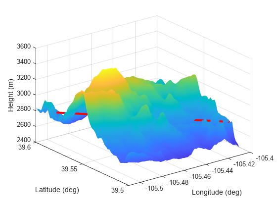
Test for occlusion.
ht1 = height(srf,[39.59 -105.5])
ht1 =
2.7962e+03
ht2 = height(srf,[39.51 -105.41])
ht2 =
2.7718e+03
occlusion(srf,[39.59 -105.5 ht1],[39.51 -105.41 ht2])
ans = logical
   1
The points are occluded. The line between the two points passes through the surface as shown.
plot3([-105.5 -105.41],[39.59 39.51], [ht1 ht2],'r','LineWidth',3)
Version History
Introduced in R2022a