Send and Receive CAN Data in Simulink Using ROS 2-CAN Bridge Node
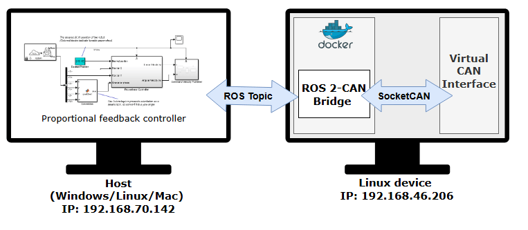
This example shows how to design and test a feedback control algorithm in Simulink® using CAN messages exchanged between the CAN and ROS 2 network. The connection is established through a ROS 2–CAN bridge node deployed on a remote Linux® device.
The workflow includes:
Configuring virtual CAN interfaces on the Linux device and starting a Docker® container to host the ROS 2–CAN bridge node.
Creating and deploying a ROS 2-CAN bridge node to relay messages between the CAN and ROS 2 networks.
Designing the feedback control algorithm in Simulink and testing it using CAN data provided by the bridge node.
The following diagram illustrates the setup, showing how the CAN controller communicates with ROS 2 model through the bridge node:
Prerequisites
To follow this example, you must have:
Simulink Coder™ installed to generate code for the ROS 2-CAN bridge node.
A Linux® device that supports SocketCAN for deploying the ROS 2-CAN bridge node.
Docker installed and configured on the Linux device. For instructions, see Install and Set Up Docker for ROS, ROS 2, and Gazebo.
Note: If you are deploying a ROS 2 node for the first time, see the ROS Toolbox System Requirements page for details on setting up your environment.
Set Up Virtual CAN Interfaces
This example requires two virtual CAN interfaces on your Linux device: one for receiving CAN frames and another for sending them. These virtual CAN interfaces will be accessed by the Docker container and ROS 2-CAN bridge node.
To create the CAN interfaces, run the following commands in the Linux terminal:
$ sudo modprobe vcan
$ sudo ip link add vcan0 type vcan
$ sudo ip link add vcan1 type vcan
This example is designed to use the CAN interfaces vcan0 and vcan1 by default. You can change these interface names if required.
Start Docker Container
With the virtual CAN interfaces configured and the Docker image created, start the container to run the ROS 2–CAN bridge node.
To start a Docker container, run the following command in Linux device terminal:
$ docker run -it --net=host -v /dev/shm:/dev/shm --name ros2_can_bridge <image-name>
Here, 'ros2_can_bridge' is the name of the Docker container. Replace the <image-name> with the name of the Docker image created in the Prerequisites section.
Get IP Address of Docker Container
While the Docker container is running, obtain the IP address of the Docker container running on the linux device. This IP address is necessary for establishing an SSH connection and later deploy the bridge node from Simulink. Note that the IP address of the Docker container is the same as the IP of the host machine.
To retrieve this IP address, run the following command in the Linux deivce terminal:
$ ifconfig
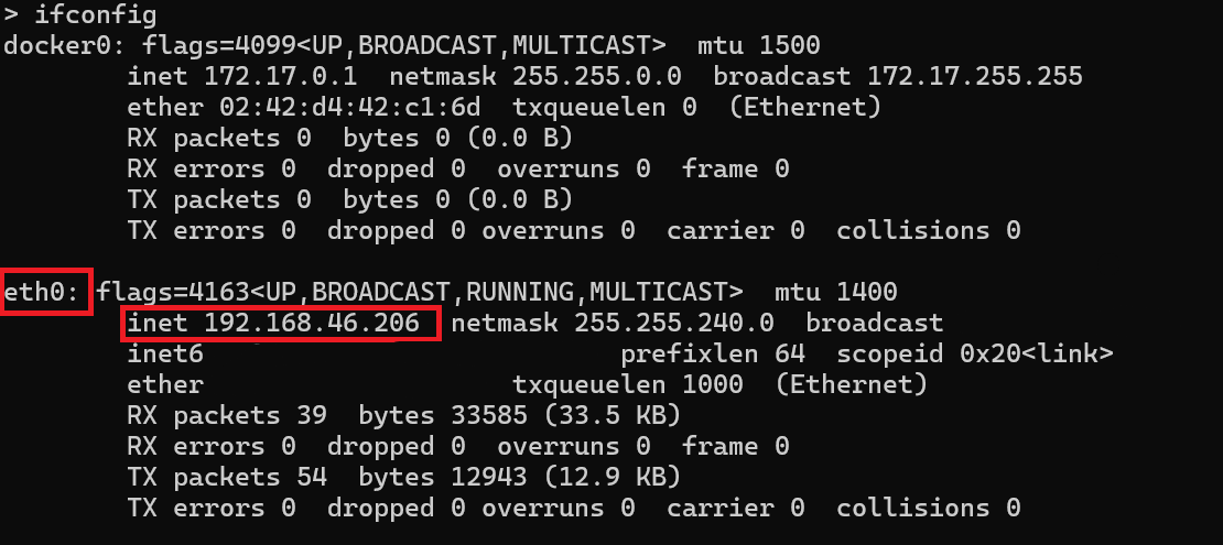
The network connection type can vary depending on how host is connected to the remote device. While this example uses an Ethernet connection (eth0), in many cases, a wireless connection (wlan0) may be applicable.
Inspect Simulink Model for ROS 2-CAN Bridge
With the Linux device configured and the Docker container running, switch back to the host and launch Simulink to inspect the ROS 2-CAN bridge model before deployment.
Open the ROS2CANBridge.slx model:
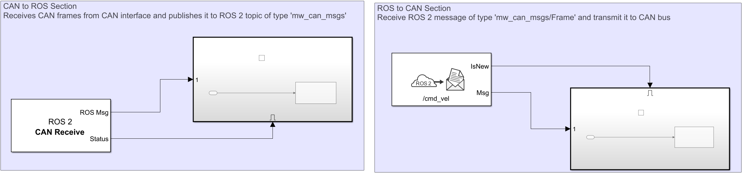
open_system("ROS2CANBridge");This model contains two sections:
1. CAN to ROS section: Reads the CAN frames from specified CAN interface using CAN Receive block, then publishes the CAN frame to ROS 2 network using the ROS 2 Publish block. The provided model is configured to read from CAN device/interface 'vcan0' and on arrival of new message, it publishes the message on topic '/odom' of type 'mw_can_msgs/Frame'.
2. ROS to CAN section: Subscribes a ROS 2 message using the ROS 2 Subscribe block, then writes back the CAN frame to specified CAN interface using the CAN Transmit block. The model contains ROS 2 Subscribe block that receives messages on topic '/cmd_vel' of type 'mw_can_msgs/Frame' and transmits it to CAN device/interface 'vcan1'.
After inspecting the model, proceed to deploy it as a ROS 2 node in the Docker container so that the CAN controller and ROS 2 network can start exchanging data.
Deploy ROS 2-CAN Bridge Node on Docker Container
In this step, configure the ROS2CANBridge model to generate C++ code and deploy it as a standalone ROS 2 node in the Docker container.
Select ROS tab from Simulink toolstrip.
Set Deploy to as Remote Device.
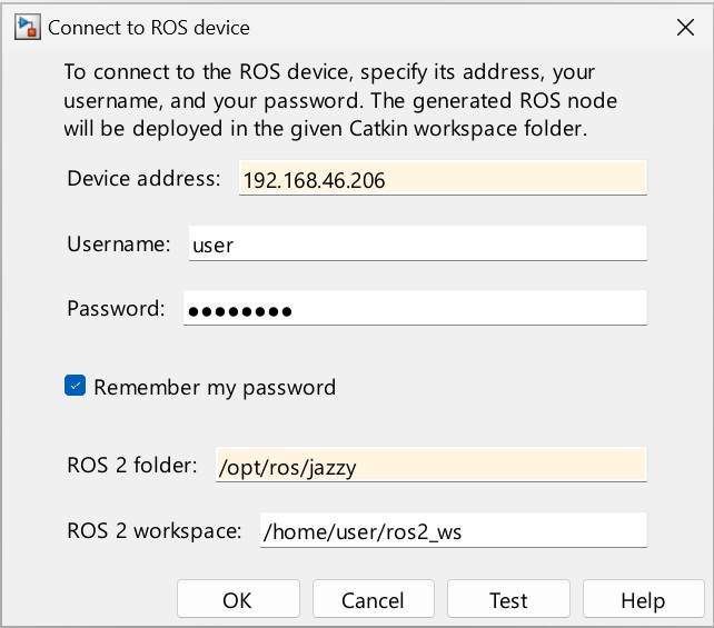
Click Manage Remote Device, and fill in the Device address, Username and Password. For Docker container, the
Device addressis Docker container IP,Usernameis 'user'andPasswordis 'password'.
Finally, to build and run the model, go to the ROS tab → Deploy section → select Build and Run. This compiles the code and runs the ROS 2-CAN bridge node in the Docker container.
Verify Node Deployment
The deployed node uses ROS_DOMAIN_ID set to 25. On the host, run the following command in MATLAB command window and verify that the /odom and /cmd_vel topics from the ROS 2-CAN bridge node are visible:
ros2 topic list DomainID 25
/parameter_events
/rosout
Inspect Simulink Model for Proportional Controller
With the ROS 2-CAN bridge node running, you can now test the feedback control algorithm.
Open the ROS2FeedbackControl.slx model, which simulates a proportional controller for a differential-drive mobile robot. At each step, the algorithm steers the robot toward the target and moves it forward.
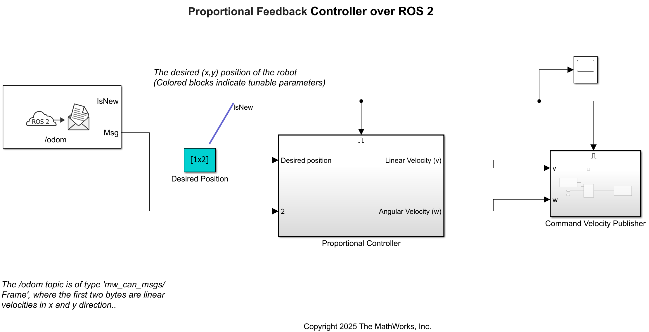
After inspecting the model, proceed to simulate it to start exchanging data with ROS 2-CAN bridge node.
Run Proportional Controller Model
With the ROS 2–CAN bridge node deployed on the Docker container and publishing odometry data from the CAN bus to the ROS 2 network, you can now run the proportional controller to verify interaction between both networks.
Open the model:
open_system("ROS2FeedbackControl");Click Run to simulate the model.
Verify ROS 2-CAN Communication
On the Docker container, with both the ROS 2-CAN bridge node (on Docker container) and feedback control model (on host) running, send odometry data to vcan0 and check the controller output on vcan1.
Send Odometry Data from CAN Interface
Open a terminal in Docker container by running the following command in Linux device:
$ docker exec -it ros2_can_bridge /bin/bash
In a Docker container terminal, run the following command to send a CAN frame:
$ cansend vcan0 100#000000
The above command follows the format "cansend <can-interface-name> <can-msg-id>#{data}", where,
cansend is used to send message to specified CAN Interface.
<can-interface> is the device, or CAN interface name (eg- vcan0, can0, and more).
<can-msg-id> is identifier for the message.
{data} is array of bytes with max length as 8.
This command sends a CAN frame to vcan0 with pose (x=0, y=0, yaw=0).
Receive Command Velocity on CAN Interface
Now, monitor the output command velocity on vcan1, open another Docker container terminal and execute the below command:
$ candump vcan1
For more details on cansend and candump command, check out in this documentation.
This example also supports additional workflows, including:
Physical CAN Hardware: While this example uses a virtual CAN bus, it can also be run with physical CAN hardware.
Message Types: By default, the example uses ROS messages as the output for CAN Receive and the input for CAN Transmit. Alternatively, you may select other options such as 'Raw Data' or 'CAN Msg'.