Tire (Magic Formula)
Tire defined by Magic Formula coefficients
Libraries:
Simscape /
Driveline /
Tires & Vehicles
Description
The Tire (Magic Formula) block represents a tire with longitudinal behavior given by the Magic Formula [1], an empirical equation based on four fitting coefficients. You can model tire dynamics under constant or variable pavement conditions. You can easily visualize the longitudinal friction force with respect to the wheel slip. To view the figure, click the Plot friction force versus slip hyperlink in the Description section of the block dialog box.

The longitudinal direction of the tire is the same as its direction of motion as it rolls on pavement. This block is a structural component based on the Tire-Road Interaction (Magic Formula) block.
To increase the fidelity of the tire model, you can specify properties such as compliance, inertia, rolling resistance, and varying effective rolling radius. However, these properties increase the complexity of the tire model and can slow down simulation. Consider neglecting tire compliance and inertia if simulating the model in real time or if preparing the model for hardware-in-the-loop (HIL) simulation.
Tire Model
The block treats the tire as a rigid wheel-tire combination that is in contact with the
road and subject to slip. When torque drives the wheel axle, the tire transmits
longitudinal force, Fx, to the road. The
tire transfers the resulting reaction as a force back on the wheel. This action
rotates the wheel to generate longitudinal motion. If you model tire compliance, the
tire also flexibly deforms under load. If you set the Effective rolling
radius model to Load and velocity dependent (Magic
Formula), the tire radius also changes depending on the load and
rotational velocity.
The figure shows the forces acting on the tire. The table defines the tire model variables.
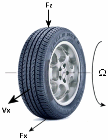
Tire Model Variables
| Symbol | Description |
|---|---|
| rw | Tire rolling radius. |
| Vx | Wheel hub longitudinal velocity. |
| u | Tire longitudinal deformation. |
| Ω | Wheel angular velocity. |
| Contact point angular velocity. If there is no tire longitudinal deformation, . | |
| Tire tread longitudinal velocity. Typically, the tire tread longitudinal velocity has a component due to tire rotation, rwΩ, and an optional component due to tire deformation, . | |
| Contact patch slip velocity. If there is no tire longitudinal compliance, . | |
| Wheel slip for a tire without compliance. | |
| Vth | Wheel hub threshold velocity. |
| VXLOW | Lower boundary of slip denominator. |
| Fz | Vertical load on tire. |
| Fx | Longitudinal force exerted on the tire at the contact point. |
| Tire longitudinal stiffness under deformation. | |
| Tire longitudinal damping under deformation. | |
| Iw | Wheel-tire inertia, such that the effective mass is equal to |
| τdrive | Torque applied by the axle to the wheel. |
Tire Kinematics and Response
You can model roll, slip, and deformation.
The equation for translational motion of a non-slipping, non-compliant tire is . When tires experience slip, they develop a longitudinal force, Fx.
The contact patch slip velocity is . For a tire without compliance, u = 0. The unsmoothed contact patch slip is
and the block saturates the slip denominator as
where VXLOW is the Lower boundary of slip denominator, VXLOW parameter. The block smoothly transitions |Vx| to VXLOW over the transition regions -VXLOW - Vth/2 < Vx < -VXLOW + Vth/2 and VXLOW - Vth/2 < Vx < VXLOW + Vth/2. The block saturates slip according to
where kpumin is the Minimum valid wheel slip, KPUMIN parameter and kpumax is the Maximum valid wheel slip, KPUMAX parameter. The block transitions k over the regions kpumin - kth/2 < k < kpumin + kth/2 and kpumax - kth/2 < k < kpumax + kth/2. The block defines the slip smoothing threshold as
For this equation, a locked, sliding wheel has k = -1. For perfect rolling, k = 0.
When you set Compliance to Specify stiffness
and damping, the block treats the tire as flexible. When the
tire deforms, the tire-road contact point turns at a slightly different angular
velocity, Ω′, from the wheel velocity, Ω,
which generates contact patch slip. The block defines the deforming tire as a
translational spring-damper of stiffness,
CFx,
and damping,
bFx.
When you set Compliance to No compliance - Suitable for
HIL simulation, , and there is no tire longitudinal deformation at any time in
the simulation, such that .
Tire and Wheel Dynamics
The block is equivalent to this component diagram. The block simulates both transient and steady-state behavior and represents starting and stopping. The Translational Spring and Translational Damper blocks are equivalent to the tire stiffness CFx and damping bFx, respectively. The Tire-Road Interaction (Magic Formula) block represents the longitudinal force Fx on the tire as a function of Fz, and k using the Magic Formula, where k is the independent slip variable and Fz is the input signal at port N.
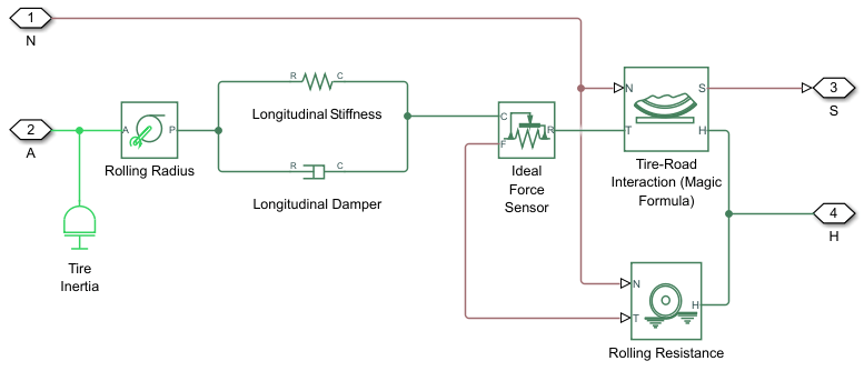
The block labeled Rolling Radius is the tire rolling radius
rw. The inertia value is the
effective inertia, . The tire characteristic function
f(k′,
Fz) determines the longitudinal force
Fx. Together with the driveshaft
torque applied to the wheel axis, Fx
determines the wheel angular motion and longitudinal motion.
When you do not model tire compliance, the block omits the Longitudinal
Stiffness and Longitudinal Damper blocks in the
diagram, and contact variables revert to wheel variables. In this case, the tire
effectively has infinite stiffness, and port P of Rolling Radius
connects directly to port C of Ideal Force
Sensor block.
When you set Rolling Resistance to a setting other than
Pressure and velocity dependent (Magic Formula), the
block omits the Ideal Force Sensor block and
connection T of the Rolling Resistance
block. When you set Compliance to No compliance
- Suitable for HIL simulation, Port P of the
Rolling Radius connects directly to the Ideal force sensor
port C or port T of the Tire-Road
Interaction (Magic Formula) block.
Effective Rolling Radius
The block determines an effective rolling radius to account for centrifugal growth and reduction due to loading such that
where:
rw is the effective rolling radius.
RΩ is the centrifugal growth of the free tire radius.
Fz is the vertical load on the tire.
Fz0 is the Tire nominal vertical load, FNOMIN parameter.
cz is the Vertical stiffness parameter.
Ω is the wheel rotational velocity.
The quantities Fz and Ω vary with time.
These quantities correspond to TIR file values and block parameters:
| Variable | TIR File Identifier | Parameter Name |
|---|---|---|
| Breff | BREFF | Low load stiffness effective rolling radius, BREFF |
| Dreff | DREFF | Peak value of effective rolling radius, DREFF |
| Freff | FREFF | High load stiffness effective rolling radius, FREFF |
| qre0 | Q_RE0 | Ratio of nominal tire radius with non-rolling free tire radius, Q_RE0 |
| qv1 | Q_V1 | Tire radius increase with speed, Q_V1 |
Note
If your TIR file does not provide Q_RE0 and
Q_V1, set these values to 1 and 0, respectively. The
sdlUtility.tirread function handles this
automatically.
Assumptions and Limitations
The block assumes only longitudinal motion and includes no camber, turning, or lateral motion.
Tire compliance implies a time lag in the response of the tire to the forces on it. Time lag simulation increases model fidelity but reduces simulation performance. See Adjust Model Fidelity.
Examples
Ports
Input
Output
Conserving
Parameters
More About
References
[1] Besselink, I. J.M., A. J.C. Schmeitz, and H. B. Pacejka. “An Improved Magic Formula/Swift Tyre Model That Can Handle Inflation Pressure Changes.” Vehicle System Dynamics 48, no. sup1 (December 2010): 337–52. https://doi.org/10.1080/00423111003748088.
[2] Pacejka, H. B. Tire and Vehicle Dynamics. Elsevier Science, 2005.

