主要内容

Complex Highpass FIR

R2026b

Design complex highpass finite impulse response filter

Description

A highpass filter attenuates the energy of an input signal below a specified frequency threshold. A finite impulse response (FIR) filter computes an output signal as a running weighted average of input samples. A complex filter is characterized by complex-valued coefficients and processes the input signal along positive and negative frequencies.

To design a Complex Highpass FIR filter, specify combinations of the parameters in the diagram. Click a parameter for more information.

Signal Processing Toolbox™ provides different ways to design complex highpass FIR filters:

All of these methods return digitalFilter objects. If you have a DSP System Toolbox™ license, you can generate your design as a filter System object™ and include additional design options.

For other ways to design complex highpass FIR filters using MATLAB, see cfirpm.

Examples

expand all

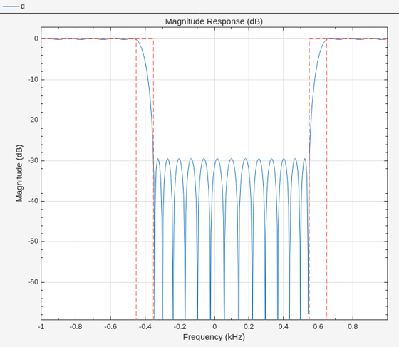
To design the filter at the command line or in a script, use the designfilt function with "complexhighpassfir" as the first argument. Use name-value arguments to specify your design further.

d = designfilt("complexhighpassfir", ... % Response type
    SampleRate=2000, ...                 % Sample rate
    FilterOrder=30, ...                  % Filter order
    PassbandFrequency1=-450, ...         % Frequency constraints
    PassbandFrequency2=650, ...
    TransitionWidth=100, ...
    PassbandWeight1=2, ...               % Design method options
    StopbandWeight=1, ...
    PassbandWeight2=2);
filterAnalyzer(d)
To design the filter using the Filter Designer app:

  1. In the Response gallery of the Designer tab in the app toolstrip, select Complex Highpass FIR.

  2. Specify the filter using the options in the Filter Parameters table:

    • In Sample Rate, specify Frequency units as Hz and Input sample rate (Hz) as 2000.

    • Under Filter Order, specify the Order as 30.

    • Under Frequency Specifications, specify:

      • Passband frequency 1 as -450 Hz

      • Passband frequency 2 as 650 Hz

      • Transition width as 100 Hz

    • Under Algorithm, select Equiripple. Under Algorithm Options, specify:

      • Passband weight 1 as 2

      • Stopband weight as 1

      • Passband weight 2 as 2

  3. In the Filter section of the Designer tab, click Update Filter.
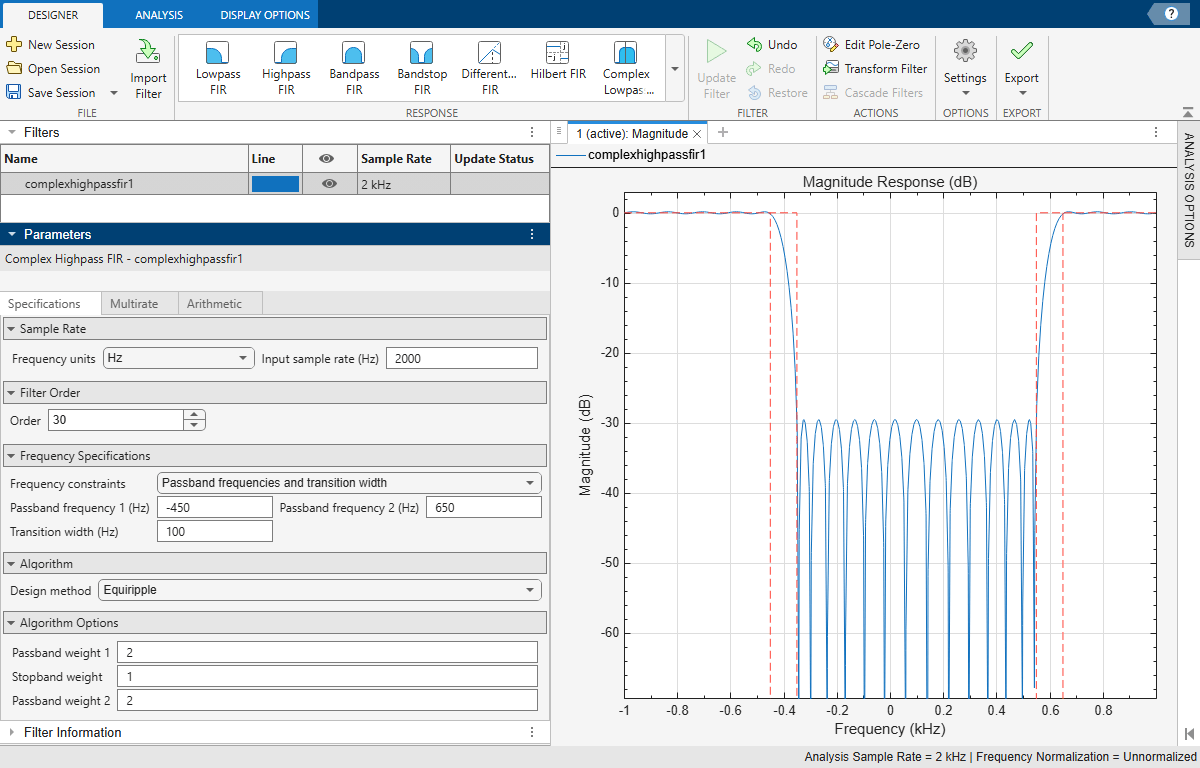
    Complex highpass FIR filter design using Filter Designer app

  4. Export code to create your digital filter. On the toolstrip, click Export and select Generate MATLAB function > Digital Filter Object. The code appears in the editor.

    function designedFilter = complexhighpassfir1filt
    
    designedFilter = designfilt('complexhighpassfir', ...
        'FilterOrder',30,'PassbandFrequency1',-450, ...
        'PassbandFrequency2',650,'TransitionWidth',100, ...
        'SampleRate',2000,'PassbandWeight1',2, ...
        'PassbandWeight2',2);
    
    end

Parameters

expand all

Design Method

Specify the algorithm to design the filter. The available design methods correlate with the set of design specifications that you choose.

Design the filter using the Parks-McClellan algorithm. Equiripple filters have a frequency response that minimizes the maximum ripple magnitude over all bands.

designfilt FunctionFilter Designer App

Specify DesignMethod="equiripple"

In the Algorithm section of the filter parameters panel, set Design method to Equiripple

The equiripple design method supports these design parameter combinations.

Sample Rate

The sample rate you specify sets the Nyquist frequency for the filter. If you specify a sample rate Fs in hertz, the Nyquist frequency is Fs/2. If you work with normalized frequencies, the Nyquist frequency is 1.

Specify the filter sample rate as a positive scalar expressed in hertz.

designfilt FunctionFilter Designer App
  • To specify a sample rate, use the SampleRate name-value argument and input a value in hertz.

  • To work with normalized frequencies, omit the sample rate.

In the Sample Rate section of the filter parameters panel:

  • To specify a sample rate, set Frequency units to Hz and type a value for Input sample rate (Hz).

  • To work with normalized frequencies, set Frequency units to Normalized.

Filter Order

Specify the filter order N as a positive integer. Some design methods let you specify the order. Others generate minimum-order designs, which are the shortest filters that satisfy the specified constraints.

designfilt FunctionFilter Designer App

  • To specify a filter order, use the FilterOrder name-value argument and input a positive integer.

  • To use a minimum-order design, specify frequency and magnitude constraints accordingly.

In the Filter Order section of the filter parameters panel:

  • To specify a filter order, set Order mode to Specify and enter a value for Order.

  • To use a minimum-order design, set Order mode to Minimum.

Frequency Specifications

The lower passband frequency is the highest frequency in the lower passband region.

Specify the lower passband frequency as a negative scalar whose absolute value is smaller than the Nyquist frequency. If you specify a sample rate Fs in hertz, the Nyquist frequency is Fs/2. If you work with normalized frequencies, the Nyquist frequency is 1.

designfilt Function Filter Designer App
  • Use the PassbandFrequency1 name-value argument. Input the value as a negative scalar.

  • In the Frequency Specifications section of the filter parameters panel, select a set of Frequency Constraints containing Passband frequency 1 and enter a negative scalar as value.

The lower stopband frequency is the lowest frequency in the stopband region.

Specify the lower stopband frequency as a negative scalar whose absolute value is smaller than the Nyquist frequency. If you specify a sample rate Fs in hertz, the Nyquist frequency is Fs/2. If you work with normalized frequencies, the Nyquist frequency is 1.

designfilt Function Filter Designer App
  • Use the StopbandFrequency1 name-value argument. Input the value as a negative scalar.

  • In the Frequency Specifications section of the filter parameters panel, select a set of Frequency Constraints containing Stopband frequency 1 and enter a negative scalar as value.

The higher stopband frequency is the highest frequency in the stopband region.

Specify the higher stopband frequency as a positive scalar smaller than the Nyquist frequency. If you specify a sample rate Fs in hertz, the Nyquist frequency is Fs/2. If you work with normalized frequencies, the Nyquist frequency is 1.

designfilt Function Filter Designer App
  • Use the StopbandFrequency2 name-value argument. Input the value as a positive scalar.

  • In the Frequency Specifications section of the filter parameters panel, select a set of Frequency Constraints containing Stopband frequency 2 and enter a positive scalar as value.

The higher passband frequency is the lowest frequency in the higher passband region.

Specify the higher passband frequency as a positive scalar smaller than the Nyquist frequency. If you specify a sample rate Fs in hertz, the Nyquist frequency is Fs/2. If you work with normalized frequencies, the Nyquist frequency is 1.

designfilt Function Filter Designer App
  • Use the PassbandFrequency2 name-value argument. Input the value as a positive scalar.

  • In the Frequency Specifications section of the filter parameters panel, select a set of Frequency Constraints containing Passband frequency 2 and enter a positive scalar as value.

The transition band separates the stopband region from either passband region.

Specify the width of the transition band as a positive scalar smaller than the Nyquist frequency. If you specify a sample rate Fs in hertz, the Nyquist frequency is Fs/2. If you work with normalized frequencies, the Nyquist frequency is 1.

designfilt FunctionFilter Designer App
  • Use the TransitionWidth name-value argument. Input the value as a positive scalar.

  • In the Frequency Specifications section of the filter parameters panel, set Transition Width by entering a positive scalar as the value.

Design Method Options

Basic Options

Lower passband optimization weight for an Equiripple design, specified as a positive scalar.

Weights let you specify the relative importance of the passband ripple and the stopband attenuation in a filter design. By default, the passband and the stopbands are equally weighted, each with unit weight. By increasing a passband weight, you can decrease the passband ripple at the expense of decreasing the stopband attenuation.

designfilt Function Filter Designer App
  • Use the PassbandWeight1 name-value argument. Input the value as a positive scalar.

  • In the Algorithm Options section of the filter parameters panel, specify Passband Weight 1 as a positive scalar.

Stopband optimization weight for an Equiripple design, specified as a positive scalar.

Weights let you specify the relative importance of the passband ripple and the stopband attenuation in a filter design. By default, the passband and the stopbands are equally weighted, each with unit weight. By increasing the stopband weight, you can increase the attenuation of the stopband at the expense of increasing passband ripple.

designfilt Function Filter Designer App
  • Use the StopbandWeight name-value argument. Input the value as a positive scalar.

  • In the Algorithm Options section of the filter parameters panel, specify Stopband Weight as a positive scalar.

Higher passband optimization weight for an Equiripple design, specified as a positive scalar.

Weights let you specify the relative importance of the passband ripple and the stopband attenuation in a filter design. By default, the passband and the stopbands are equally weighted, each with unit weight. By increasing a passband weight, you can decrease the passband ripple at the expense of decreasing the stopband attenuation.

designfilt Function Filter Designer App
  • Use the PassbandWeight2 name-value argument. Input the value as a positive scalar.

  • In the Algorithm Options section of the filter parameters panel, specify Passband Weight 2 as a positive scalar.