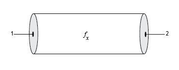
Transmission Line
Model transmission line
Libraries:
RF Blockset /
Circuit Envelope /
Elements
Description
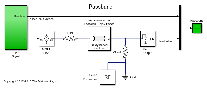
Use the Transmission Line block to model delay-based, lumped, and distributed transmission lines. Mask dialog box options change automatically to accommodate model type selection.
Examples
Transmission Lines, Delay-Based and Lumped Models
Simulate delay-based and lumped-element transmission lines.
Parameters
Main
Type of transmission line model, specified as one of these.
| Transmission Line Types | Description |
|---|---|
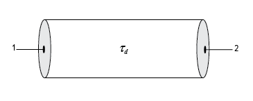
| Model transmission line with delay but no loss.
|
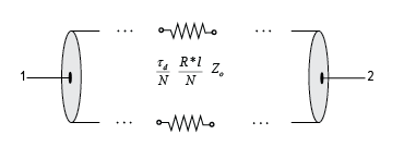
| Model transmission line with delay and loss.
|
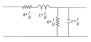
| Model transmission line with RLGC L-sections.
|
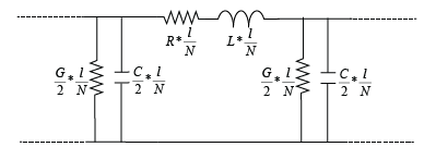
| Model transmission line with RLGC pi-sections.
|
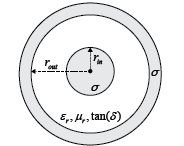
| Model transmission line as a coaxial transmission line. The cross section of a coaxial transmission line is shown in the following figure. Its physical characteristics include the radius of the inner conductor a, and the radius of the outer conductor b.
|
| Model transmission line as a coplanar waveguide. The cross section of a coplanar waveguide transmission line is shown in the following figure. Its physical characteristics include conductor width w, conductor thickness t, slot width s, substrate height d, and relative permittivity constant ε.
|
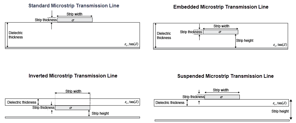
| Model transmission line as a standard, embedded, inverted, or suspended microstrip transmission line. The cross-sections of standard, embedded, inverted, and suspended microstrip transmission lines are shown here. The physical characteristics of such a transmission line include microstrip width w, microstrip thickness t, dielectric thickness d, and relative permittivity constant ε.
|
| Model transmission line as stripline transmission line. The cross-section of a stripline transmission line is shown in this figure. Its physical characteristics include strip width w, strip thickness t, dielectric thickness h, and relative permittivity constant ε.
|
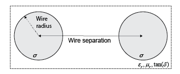
| Model transmission line as two-wire transmission line. The cross-section of a two-wire transmission line is shown in the following figure. Its physical characteristics include the radius of wires a, separation or physical distance between the wire centers S, and relative permittivity and permeability of the wires.
|
| Model transmission line as a parallel-plate transmission line. The cross-section of a parallel-plate transmission line is shown in the following figure. Its physical characteristics include plate width w, and plate separation d.
|
| Model transmission line as an equation-based transmission line. The transmission line, which can be lossy or lossless, is treated as a two-port linear network.
|
| Model transmission line as an RLCG transmission line. This line is defined in terms of its frequency-dependent resistance, inductance, capacitance, and conductance. The transmission line, which can be lossy or lossless, is treated as a two-port linear network.
|
Delay in the transmission line, specified as a real scalar in
s, ms,
us, or ns.
Dependencies
To enable this parameter, choose one of the following:
Delay-based and losslessin Model type.Delay-based and lossyin Model type.
Impedance of the transmission line, specified as a real scalar in
Ohm, kOhm,
MOhm, or
GOhm.
Dependencies
To enable this parameter, choose one of the following:
Delay-based and lossless,Delay-based and lossy, orEquation-basedin Model type.Lumped parameter L-sectionorLumped parameter Pi-sectionin Model type andBy characterisitc impedance and capacitancein Parameterization.
Resistance per unit length of the transmission line, specified as a
positive scalar in Ohm/m,
kOhm/m,
MOhm/m, or
GOhm/m.
Dependencies
To enable this parameter, choose one of the following:
Delay-based and lossyorRLCGin Model type.Lumped parameter L-sectionorLumped parameter Pi-sectionin Model type andBy characterisitc impedance and capacitancein Parameterization.
Number of segments in the transmission line, specified as a positive scalar.
Dependencies
To enable this parameter, choose one of the following:
Delay-based and lossyin Model type.Lumped parameter L-sectionorLumped parameter Pi-sectionin Model type andBy characterisitc impedance and capacitanceorBy inductance and capacitancein Parameterization.
Type of parameters to model segments in transmission line, specified
as By characterisitc impedance and capacitance or
By inductance and capacitance.
Dependencies
To enable this parameter, select Lumped parameter
L-section or Lumped parameter
Pi-section in Model
type.
Capacitance per unit length of the transmission line, specified as a
positive scalar in F/m,
mF/m, uF/m,
nF/m, or
pF/m.
Dependencies
To enable this parameter, choose Lumped parameter
L-section, Lumped parameter
Pi-section, or RLCG in
Model type.
Conductance per unit length of the transmission line, specified as a
positive scalar in S/m,
mS/m, uS/m, or
nS/m.
Dependencies
To enable this parameter, choose Lumped parameter
L-section, Lumped parameter
Pi-section, or RLCG in
Model type.
Inductance per unit length of the transmission line, specified as a
positive scalar in H/m,
mH/m, uH/m, or
nH/m.
Dependencies
To enable this parameter, choose one of the following:
Lumped parameter L-section, orLumped parameter Pi-sectionin Model type andBy inductance and capacitancein Parameterization.RLCGin Model type
Outer radius of coaxial transmission line, specified as a positive
scalar in m, cm,
mm, um,
in, or
ft.
Dependencies
To enable this parameter, choose
Coaxial in Model
type.
Inner radius of coaxial transmission line, specified as a positive
scalar in m, cm,
mm, um,
in, or
ft.
Dependencies
To enable this parameter, choose
Coaxial in Model
type.
Physical width of the conductor, specified as a positive scalar in
m, cm,
mm, um,
in, or
ft.
Dependencies
To enable this parameter, choose Coplanar
waveguide in Model
type.
Physical width of the slot, specified as a positive scalar in
m, cm,
mm, um,
in, or
ft.
Dependencies
To enable this parameter, choose Coplanar
waveguide in Model
type.
Select this parameter to add an infinite-bottom conductor to your coplanar waveguide transmission line.
Dependencies
To enable this parameter, set Model type to
Coplanar waveguide.
Type of microstrip transmission line, specified as Standard, Embedded, Inverted, or Suspended.
Dependencies
To enable this parameter, set Model type to
Microstrip.
Width of the microstrip transmission line, specified as a positive
scalar in m, cm,
mm, um,
in, or
ft.
Dependencies
To enable this parameter, set Model type
toMicrostrip.
Physical thickness of the conductor, specified as a nonnegative scalar
in m, cm,
mm, um,
in, or
ft.
Dependencies
To enable this parameter, choose Coplanar
waveguide or Microstrip
in Model type.
Strip height of the inverted, suspended, or embedded microstrip
transmission line, specified as a positive scalar in
m, cm,
mm, um,
in, or
ft.
Dependencies
To enable this parameter, choose
Microstrip in Model
type and choose Inverted,
Suspended, or
Embedded in
Structure.
Radius of the conducting wires of the two-wire transmission line,
specified as a positive scalar in m,
cm, mm,
um, in, or
ft.
Dependencies
To enable this parameter, choose
Two-wire in Model
type.
Physical distance between the conducting wires of the two-wire
transmission line, specified as a positive scalar in
m, cm,
mm, um,
in, or
ft.
Dependencies
To enable this parameter, choose
Two-wire in Model
type.
Width of the parallel-plate transmission line, specified as a positive
scalar in m, cm,
mm, um,
in, or
ft.
Dependencies
To enable this parameter, choose
Parallel-plate in Model
type.
Thickness of the dielectric separating the plates, specified as a
positive scalar in m,
cm, mm,
um, in, or
ft.
Dependencies
To enable this parameter, choose
Parallel-plate in Model
type.
Propagation velocity of a uniform plane wave on the transmission line, specified as a positive scalar in meters per second.
Dependencies
To enable this parameter, choose
Equation-based in Model
type.
Reduction in strength of the signal as it travels over the transmission line, specified as a positive scalar in meters per second.
Dependencies
To enable this parameter, choose
Equation-based in Model
type.
Modeling frequencies, specified as a positive scalar or vector in
Hz, kHz,
MHz, or
GHz.
Dependencies
To enable this parameter, choose
Equation-based or
RLCG in Model
type.
Interpolation method used to calculate the values at the modeling
frequencies, specified as Linear,
Spline, or
Cubic.
Dependencies
To enable this parameter, choose
Equation-based or
RLCG in Model
type.
Conductivity of conductor, specified as a scalar in
S/m, mS/m,
uS/m, or
nS/m.
Dependencies
To enable this parameter, choose
Coaxial, Coplanar
waveguide, Microstrip,
Two-wire or
Parallel-plate in Model
type.
Thickness of the dielectric on which the conductor resides, specified
as a positive scalar in m,
cm, mm,
um, in, or
ft.
Default values of the dielectric thickness of coplanar waveguide, standard, embedded, inverted, and suspended microstrip transmission lines are listed in this table.
| Model Type | Structure | Default Dielectric Thickness in mm |
|---|---|---|
Coplanar waveguide | N.A. | 0.635 |
Microstrip | Standard and
Inverted | 0.635 |
'Suspended' | 0.3175 | |
'Embedded' | 1.37 |
Dependencies
To enable this parameter, set Model type to
Microstrip or Coplanar
waveguide.
Relative permeability of the dielectric, specified as a scalar.
Dependencies
To enable this parameter, set Model type to
Coaxial,
Two-wire, or
Parallel-plate.
Relative permittivity of the dielectric, specified as a scalar.
Dependencies
To enable this parameter, set Model type to
Coaxial, Coplanar
waveguide, Microstrip,
Two-wire, or
Parallel-plate.
Loss tangent of the dielectric, specified as a scalar.
Dependencies
To enable this parameter, set Model type to
Coaxial, Coplanar
waveguide, Microstrip,
Two-wire, or
Parallel-plate.
Physical length of the transmission line or l,
specified as a positive scalar in m,
cm, mm,
um, in, or
ft.
Dependencies
To enable this parameter, choose one of the following:
Delay-based and lossy,Coaxial,Coplanar waveguide,Microstrip, orTwo-wire,Parallel-plate,Equation-based, orRLCGin Model type.Lumped parameter L-sectionorLumped parameter Pi-sectionin Model type andBy characterisitc impedance and capacitanceorBy inductance and capacitancein Parameterization.
Type of stub, specified as Not a stub,
Shunt, or
Series. See Parameter Calculations for Transmission Line with Stub.
Dependencies
To enable this parameter, choose
Coaxial, Coplanar
waveguide, Microstrip
Two-wire,
Parallel-plate,
Equation-based, or
RLCG in Model
type.
Type of termination for stub, specified as
Open or
Short.
Dependencies
To enable this parameter, choose Series
or Shunt in Stub
mode.
Select this parameter to internally ground and hide the negative terminals. To expose the negative terminals, clear this parameter. By exposing these terminals, you can connect them to other parts of your model.
By default, this option is selected.
Modeling
Options to model S-parameters, specified as:
Frequency domain– Computes the baseband impulse response for each carrier frequency independently. This technique is based on convolution. There is an option to specify the duration of the impulse response. For more information, see Compare Time and Frequency Domain Simulation Options for S-parameters.Time domain– Computes the analytical rational model that approximates the whole range of the data.
For the Amplifier, Antenna, and S-Parameters blocks, the default
value is Time domain. For the Transmission
Line block, the default value is Frequency
domain.
Select Automatically estimate impulse response duration to calculate impulse response duration automatically. Clear the selection to specify impulse response duration.
Dependencies
To enable this parameter, choose Frequency domain in
Modeling options.
Manually specify impulse response duration, specified as a positive scalar in
s, ms,
us, or ns.
Dependencies
To enable this parameter, clear Automatically estimate impulse response duration.
Fitting options for rationalfit, specified as Share all
poles, Share poles by columns, or
Fit
                individually
.
For the Amplifier block, the default value is Fit
individually. For the S-parameters block and
Transmission Line block, the default value is Share all
poles.
Dependencies
To enable this parameter, choose Time domain in
Modeling options.
Relative error acceptable in rational fit output, specified as a real scalar in decibels.
Dependencies
To enable this parameter, choose Time domain in
Modeling options.
Shows values of Number of independent fits, Number of required poles, and Relative error achieved (dB).
When modeling using Time domain, the Plot in
Visualization tab plots the data defined in Data
Source and the values in the rationalfit
function.
Dependencies
To enable this parameter, choose Time domain in
Modeling options.
Note
Modeling tab is enabled for all transmission line types except
Delay-based and lossless,
Delay-based and lossy, Lumped
parameter L-section, and Lumped parameter
pi-section.
More About
The following auxiliary equations are used for ABCD-parameter calculations.
where
In these equations:
a is the radius of the inner conductor.
b is the radius of the outer conductor.
σcond is the conductivity in the conductor.
μ is the permeability of the dielectric.
ε is the permittivity of the dielectric.
ε″ is the imaginary part of ε, ε″ = ε0εrtan δ, where:
ε0 is the permittivity of free space.
εr is the Relative permittivity constant parameter value.
tan δ is the Loss tangent of dielectric parameter value.
δcond is the skin depth of the conductor, which the block calculates as .
f is a vector of internal modeling frequencies.
Z0 is the specified characteristic impedance.
k is a vector whose elements correspond to the elements of the input vector,
freq. The block calculates k from the specified parameters as k = αa + iβ, where αa is the attenuation coefficient and β is the wave number. The attenuation coefficient αa is related to the specified loss, α, byThe wave number β is related to the specified phase velocity, Vp, by
The phase velocity VP is also known as the wave propagation velocity.
When modeling distributed transmission lines, the block first calculates ABCD-parameters at a set of internal frequencies. The ABCD-parameters are converted S-parameters for simulation.
The block calculates the ABCD-parameters from the physical length of the transmission line, d, and the complex propagation constant, k, using the following set of equations:
When you set the Stub mode parameter in the mask dialog box
to Shunt, the two-port network consists of a transmission line in
series with a stub. You can terminate the stub with a short circuit or an open
circuit as shown in the following figure.

Zin is the input impedance of the shunt circuit. The ABCD-parameters for the shunt stub are calculated as
When you set the Stub mode parameter in the mask dialog box
to Series, the two-port network comprises a series transmission
line. You can terminate this line with either a short circuit or an open circuit as
shown here.
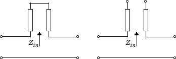
Zin is the input impedance of the series circuit. The ABCD-parameters for the series stub are:
Tips
In general, blocks that model delay effects rely on signal history. You can minimize numerical error that occur due to a lack of signal history at the start of a simulation. To do so, in the Configuration Parameters dialog box Solver pane you can specify an Initial step size. For models with delay-based Transmission Line blocks, use an initial step size that is less than the value of the Delay parameter.
References
[1] Sussman-Fort, S. E., and J. C. Hantgan. “SPICE Implementation of Lossy Transmission Line and Schottky Diode Models.” IEEE Transactions on Microwave Theory and Techniques.Vol. 36, No.1, January 1988.
[2] Pozar, David M. Microwave Engineering. Hoboken, NJ: John Wiley & Sons, Inc., 2005.
[3] Gupta, K. C., Ramesh Garg, Inder Bahl, and Prakash Bhartia. Microstrip Lines and Slotlines, 2nd Edition, Norwood, MA: Artech House, Inc., 1996.
[4] Ludwig, Reinhold and Pavel Bretchko. RF Circuit Design: Theory and Applications. Englewood Cliffs: NJ: Prentice-Hall, 2000.
[5] True, Kenneth M. “Data Transmission Lines and Their Characteristics.” National Semiconductor Application Note 806, April 1992.
Version History
Introduced in R2012aThe Time domain (rationalfit) parameter value in the
Modeling options parameter has been renamed to
Time domain in the Transmission Line
block.
When you open a model created before R2024b containing an Transmission
Line block, the parameter name displays as Time
domain.
The Substrate height, Relative permittivity constant, and Relative permeability constant parameters in the Transmission Line block have been renamed to Dielectric thickness, Relative permittivity of dielectric, and Relative permeability of dielectric, respectively.
When you open a model created before R2022a containing the Transmission Line block, the software replaces the old parameters names with the new ones.
Use the Transmission Line block to model:
Embedded, inverted, and suspended microstrip transmission lines
Conductor-backed coplanar waveguide transmission lines
Stripline transmission lines
See Also
MATLAB Command
You clicked a link that corresponds to this MATLAB command:
Run the command by entering it in the MATLAB Command Window. Web browsers do not support MATLAB commands.
选择网站
选择网站以获取翻译的可用内容,以及查看当地活动和优惠。根据您的位置,我们建议您选择:。
您也可以从以下列表中选择网站:
如何获得最佳网站性能
选择中国网站(中文或英文)以获得最佳网站性能。其他 MathWorks 国家/地区网站并未针对您所在位置的访问进行优化。
美洲
- América Latina (Español)
- Canada (English)
- United States (English)
欧洲
- Belgium (English)
- Denmark (English)
- Deutschland (Deutsch)
- España (Español)
- Finland (English)
- France (Français)
- Ireland (English)
- Italia (Italiano)
- Luxembourg (English)
- Netherlands (English)
- Norway (English)
- Österreich (Deutsch)
- Portugal (English)
- Sweden (English)
- Switzerland
- United Kingdom (English)

