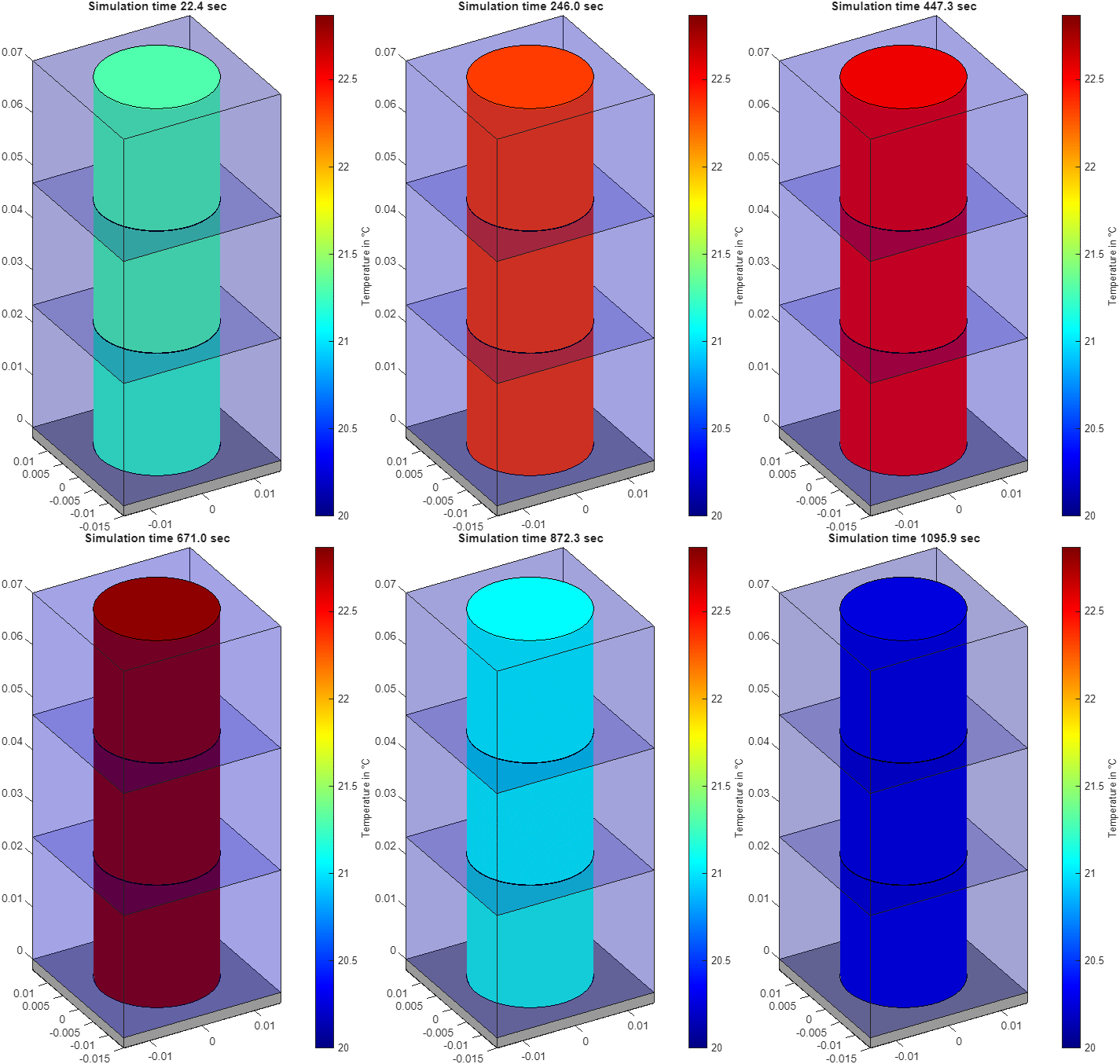
Model Thermally-Discretized Cell with Immersion Cooling
This example shows how to implement a thermally-discretized cylindrical cell with an immersion cooling strategy.
This example discretizes the cell along its height into three cylindrical elements of equal size. Each element connects to a separate volume that represents the coolant surrounding the cell. This example uses water as a coolant. The bottom element of the cell lays on a thin layer of aluminum, that represents the bottom of the module casing where the cell is placed.
During the simulation, a Battery CC-CV block charges the cell. At the beginning of the simulation, the battery module has a state of charge (SOC) equal to 10%. The Battery CC-CV block performs a constant-current (CC) charging until the battery reaches the limit cell voltage of 4.1 V, specified in the Maximum cell voltage (V) parameter. The block then charges the battery with a constant-voltage (CV) profile until the SOC of the battery module reaches 90%. During the charging process, the coolant flows through the three fluid volumes and cools down the cell by convection.
Open Model
Open the ImmersionCooling model.
modelname = "ImmersionCooling";
open_system(modelname);
The model comprises these fundamental elements:
Battery Equivalent Circuit block — Model the thermally-discretized cell. This example parameterizes the battery cell using the
INR_21700_P45Bpredefined parameterization from the Block Parameterization Manager.Battery CC-CV block — Implement a battery charging algorithm with constant current and constant voltage.
Three Constant Volume Chamber (TL) blocks — Represent the coolant that surrounds the cell. The chamber contains a constant volume of liquid. Pressure and temperature vary dynamically based on the net mass and energy accumulation in the volume.
Three Convective Heat Transfer blocks — Model heat transfer in a thermal network by convection due to fluid motion. These blocks account for the heat transfer between the cell and fluid.
Flow Rate Source (TL) block — Represent an ideal mechanical energy source in a thermal liquid network that moves the fluid through the volume elements.
Thermal Mass and Thermal Resistance blocks — Model an internal energy storage and a resistance in a thermal network. These blocks represent the module casing.
Probe block — Monitor the SOC of the cell and stop the simulation when the SOC reaches 90%.
Array Connection block — Concatenate different arrays of nodes into a single array of nodes. To specify the domain for the block connections, set the Domain parameter. In this example, this block acts as a mux for the Simscape™ thermal domain by concatenating all input array of thermal nodes into a single 1-D thermal array.
The ImmersionCoolingData.m file contains the parameters used in this model.
Run Simulation and View Results
Run the simulation.
immCool = sim(modelname);
This plot shows the temperature of the cell and fluid elements during the charging cycle. The fluid elements maintain a lower temperature because cold fluid enters one side while hot fluid exits the other. The temperature development of the fluid elements varies depending on the fluid type and flow characteristics.
At the start of the simulation, the temperature of the cell elements increases rapidly. This increase occurs because the cell charges with a high current during the CC phase of the CC-CV charging profile. When the Battery CC-CV block transitions to the CV phase of the cycle, the current decreases, reducing the losses in the cell. Consequently, the temperature of the cell decreases rapidly. The temperature development of the cell elements depends on the thermal mass of the cell, the applied current and losses, and the convection coefficient between the cell and fluid.

To generate this plot again, run this command:
ImmersionCoolingPlotResults;
See Also
Array Connection | Battery Equivalent Circuit | Battery CC-CV