Selector
从向量、矩阵或多维信号中选择输入元素
库:
Simulink /
Signal Routing
HDL Coder /
Signal Routing
描述
Selector 模块根据指定的索引提取输入向量、矩阵或多维信号的选定元素。提取的信号可以按不同于输入信号的方式进行组合。
基于您为输入维数参数输入的值,将显示一个索引设置表。表中的每一行对应于输入维数中的一个输入维度。对于每个维度,您可以定义要使用的信号元素。可将向量信号指定为一维信号,将矩阵信号指定为二维信号。当您配置 Selector 模块进行多维信号操作时,模块图标将发生变化。
例如,假设一个 6 维信号具有从 1 开始的索引模式。Selector 模块对话框中的表将发生变化,使每个维度都有一个对应的行。如果如下表所示定义维度,则输出为 Y = U(1:end,2:6,[1 3 5],Idx4:Idx4+7,Idx5,Idx6(1):Idx6(2)),其中 Idx4、Idx5 和 Idx6 是维度 4、5 和 6 的索引端口。有关详细信息,请参阅使用 Selector 模块从多维数组中选择元素。
| 行 | 索引选项 | 索引 | 输出大小 |
|---|---|---|---|
| 1 | 全选 | ||
| 2 | 起始索引(对话框) | 2 | 5 |
| 3 | 索引向量(对话框) | [1 3 5] | |
| 4 | 起始索引(端口) | 8 | |
| 5 | 索引向量(端口) | ||
| 6 | 起始和结束索引(端口) |
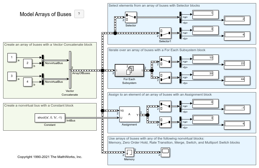
可使用总线数组作为 Selector 模块的输入信号。有关定义和使用总线数组的详细信息,请参阅使用总线数组组合非虚拟总线。
注意
Selector 模块不更改输入信号的维度(维数)。如果您需要将信号的维度更改为您指定的维度,请使用 Reshape 模块。
示例
此示例显示两个 Selector 模块,它们具有相同类型的输入信号,但有两种不同索引选项设置。
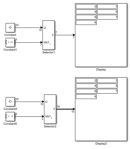
两个 Selector 模块都从输入端口的输入信号中选择 7 个值。Selector1 模块输出固定大小的信号,而 Selector2 模块输出可变大小的信号,其编译后的信号维度是 10 而不是 7。
Selector1 模块将索引选项设置为 Index vector (port),它使用来自 Constant1 的输入信号作为索引向量。输入信号的维度为 7,因此 Display 模块显示 Constant1 模块的 7 个值。Selector2 模块将输入端口大小参数设置为 10,这是 Selector2 模块的最大输入信号大小。
Selector2 模块还将索引选项设置为 Starting and ending indices (port)。然后,输出设置为输入端口大小参数的大小 (10),即使输入信号的大小为 7 也是如此。
此示例说明如何使用 Selector 模块从多维数组中选择元素。在此示例中,您使用模块的不同索引选项来选择和提取一个六维数组的元素。
打开模型。
mdl = "extractmultidimarray.slx";
open_system(mdl)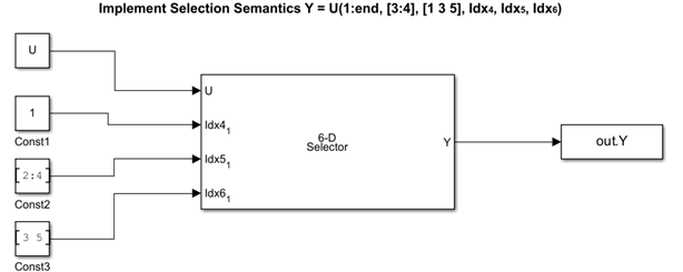
配置模块
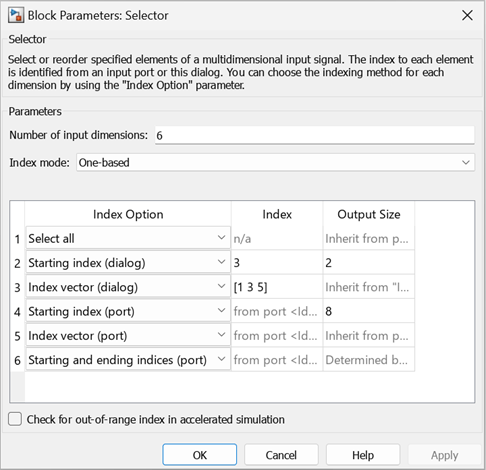
输入数组 U 是一个六维数组,维度为 6×6×6×9×7×5,采用从 1 开始的索引模式。该模型通过使用模型 PreLoadFcn 回调从 inputSignal 文件加载输入数组。您可以使用以下选择语义和不同索引选项从数组的每个维度中选择元素。在此示例中,对输入数组使用从 1 开始的索引模式。因此,行号(表的第一列)直接指示输入数组的维度。例如,第 1 行指示输入数组的维度 1,依此类推。
要提取维度 1 的所有元素,请使用
Select All。要提取维度 2 的第三个和第四个元素,请使用
Starting Index (dialog)。将索引列设置为3,将输出大小列设置为2。要提取维度 3 的第一个、第三个和第五个元素,请使用
Index vector (dialog)。将索引列设置为 [1 3 5]。要提取维度 4 的前八个元素,请使用
Starting Index (port)。连接到端口 的 Constant 模块Const1提供起始索引值1。将输出大小列设置为8。要提取维度 5 的第二个、第三个和第四个元素,请使用
Index vector (port)。连接到端口 的 Constant 模块Const2提供索引值 [2:4]。要从维度 6 中提取一定范围内的元素,请使用
Starting and ending indices (port)。选择范围是从第三个元素到第五个元素。连接到端口 的 Constant 模块Const3提供范围 [3 5]。
记录信号
运行仿真并使用 To Workspace 模块将信号记录到变量 Y。
Y = sim(mdl);
扩展示例
有界可变大小信号基本操作
此示例说明如何生成有界可变大小信号,并说明使用这些信号的一些操作。在此示例中,您使用 Selector 模块和 Switch 模块生成可变大小信号。这些信号用于数学运算、总线创建、总线选择、矩阵串联以及实现离散滤波器方程。
限制
索引参数在仿真期间不可调。如果维度的索引选项设置为索引向量(对话框) 或起始索引(对话框),并且您在模块对话框中为对应的索引指定了符号值,包括
Simulink.Parameter对象,则仿真开始时的瞬时值将在整个仿真中使用,并且该参数将在生成代码中作为内联值出现。请参阅使用模块参数值进行调优和试验。您可以使用索引端口动态调整选择索引。
端口
输入
输入信号,亦即输出信号的元素来源。
数据类型: single | double | half | int8 | int16 | int32 | int64 | uint8 | uint16 | uint32 | uint64 | Boolean | fixed point | enumerated | bus | image
外部端口,用于指定对应输出元素的选择的索引。
您可以指定自定义宽度的整数(例如,15 位整数或 23 位整数)作为索引信号值。配置整数的宽度时,必须将模式指定为定点,其中字长小于或等于 65,535,斜率等于 1,偏置等于 0。有关指定定点数据类型的详细信息,请参阅使用数据类型助手指定数据类型。
依赖关系
要启用外部索引端口,请在索引选项表的对应行中,将索引选项设置为索引向量(端口)、起始索引(端口) 或起始和结束索引(端口)。
数据类型: single | double | int8 | int16 | int32 | uint8 | uint16 | uint32
输出
根据选定或重新排序的输入信号元素生成的输出信号。
数据类型: single | double | half | int8 | int16 | int32 | int64 | uint8 | uint16 | uint32 | uint64 | Boolean | fixed point | enumerated | bus | image
参数
指定输入信号的维数。
编程用法
模块参数:NumberOfDimensions
|
| 类型:字符向量 |
值:integer
|
默认值:'1'
|
指定索引模式。如果选择 One-based,则索引 1 指定输入向量的第一个元素。如果选择 Zero-based,则索引 0 指定输入向量的第一个元素。
编程用法
模块参数:IndexMode
|
| 类型:字符向量 |
值:'One-based' | 'Zero-based'
|
默认值:'One-based'
|
按维度定义信号元素的索引方式。从列表中,选择:
全选
不需要进一步配置。所有元素都被选中。
索引向量(对话框)
启用索引列。输入元素索引向量。
索引向量(端口)
不需要进一步配置。
起始索引(对话框)
启用索引和输出大小列。在索引列中输入要选择的元素范围的起始索引,在输出大小列中输入要选择的元素数。
起始索引(端口)
启用输出大小列。在输出大小列中输入要选择的元素数。
起始和结束索引(端口)
不需要进一步配置。
使用此选项将生成可变大小的输出信号。当您更新时,输出维度设置为与输入信号的维度相同。在执行过程中,将根据提供给索引的信号来更新输出维度。
记录输出信号数据时,未选择的信号用 NaN 值填充。
可以根据需要显示索引和输出大小列。
编程用法
模块参数:IndexOptionArray
|
| 类型:字符向量元胞数组 |
值:{'Select all'} | {'Index vector (dialog)'} | {'Index vector (port)'} | {'Starting index (dialog)'} | {'Starting index (port)'} | {'Starting and ending indices (port)'} |
默认值:{'Index vector (dialog)'}
|
对于字符向量而不是字符向量元胞数组,请使用 IndexOptions。
当索引选项设置为索引向量(对话框) 时,请输入所需的每个元素的索引。
当索引选项设置为起始索引(对话框)时,请输入要选择的元素范围的起始索引。
编程用法
模块参数:IndexParamArray
|
| 类型:字符向量元胞数组 |
| 值:整数 |
默认值:{'[1 3]'}
|
对于字符向量而不是字符向量元胞数组,请使用 Indices。
指定模块输出信号的宽度。
编程用法
模块参数:OutputSizeArray
|
| 类型:字符向量元胞数组 |
| 值:整数 |
默认值:{'1'}
|
对于字符向量而不是字符向量元胞数组,请使用 OutputSizes。
指定一维信号的模块输入信号的宽度。输入 -1 将从驱动模块继承。
编程用法
模块参数:InputPortWidth
|
| 类型:字符向量 |
值:integer
|
默认值:'3'
|
指定采样时间间隔。要继承采样时间,请将此参数设置为 -1。有关详细信息,请参阅指定采样时间。
依赖关系
仅当您将此参数设置为 -1 以外的值时才可见。要了解详细信息,请参阅不建议设置采样时间的模块。
编程用法
要以编程方式设置模块参数值,请使用 set_param 函数。
| 参数: | SampleTime |
| 值: | "-1" (默认) | scalar or vector in quotes |
选中此复选框可让 Simulink® 在加速或快速加速模式下进行仿真时检查是否有任何索引值超出输入信号的相关维度的有效索引范围。如果索引超出范围,Simulink 将停止仿真并显示错误消息。
注意
如果不选中此复选框,超出范围的索引值可能导致在加速或快速加速模式下仿真期间出现未定义的行为。
无论是否选中此复选框,在普通模式仿真期间 Simulink 都会执行此检查。
编程用法
参数:RuntimeRangeChecks
|
| 类型:字符向量 |
值:'Off' | 'On' |
默认值:'Off'
|
模块特性
数据类型 |
|
直接馈通 |
|
多维信号 |
|
可变大小信号 |
|
过零检测 |
|
扩展功能
C/C++ 代码生成
使用 Simulink® Coder™ 生成 C 代码和 C++ 代码。
HDL Coder™ 提供影响 HDL 实现和综合逻辑的额外配置选项。
此模块具有一个默认 HDL 架构。
| 通用 | |
|---|---|
| ConstrainedOutputPipeline | 通过移动设计中现有延迟的方式来放置在输出端的寄存器的数量。分布式流水线不会重新分发这些寄存器。默认值为 |
| InputPipeline | 要在生成的代码中插入的输入流水线阶段数。分布式流水线和受限输出流水线可以移动这些寄存器。默认值为 |
| OutputPipeline | 要在生成的代码中插入的输出流水线阶段数。分布式流水线和受限输出流水线可以移动这些寄存器。默认值为 |
| 原生浮点 | |
|---|---|
| LatencyStrategy | 指定对于浮点运算符是否将设计中的模块映射到 |
该模块支持使用以下数据类型进行 HDL 代码生成:
| 输入端口 | 维度 | 定点 | 浮点 | 内置整数 | 总线 | 布尔 | 枚举 | 复信号 |
|---|---|---|---|---|---|---|---|---|
| Port1 | 标量 向量 矩阵(最高二维) | 是 | 半精度 单精度 双精度 | 否 | 是 | 是 | 是 | 是 |
模块参与以下 HDL 优化,以优化速度和面积。
面积优化
| 优化 | 描述 |
|---|---|
| Resource Sharing (HDL Coder) | 资源复用是一种面积优化,其中 HDL Coder 确定多个在功能上等效的资源,并用单个资源替换它们。 |
| Streaming (HDL Coder) | 流式处理是一种面积优化,其中 HDL Coder 将向量数据路径变换为标量数据路径(或多个较小的向量数据路径)。 |
速度优化
| 优化 | 描述 |
|---|---|
| Distributed Pipelining (HDL Coder) | 分布式流水线或寄存器重定时是一种速度优化,它可以移动设计中的现有延迟,以在缩减关键路径的同时保留功能性行为。 |
| Clock-Rate Pipelining (HDL Coder) | 时钟频率流水线是 HDL Coder 中的一个优化框架,它允许其他速度优化和面积优化在时钟频率下引入延迟。 |
| Adaptive Pipelining (HDL Coder) | 自适应流水线优化创建带寄存器的模块模式或组合,通过在设计中的模块中插入流水线寄存器,可以提高可实现的时钟频率并减少 FPGA 板上的面积使用量。 |
PLC 代码生成
使用 Simulink® PLC Coder™ 生成结构化文本代码。
定点转换
使用 Fixed-Point Designer™ 设计和仿真定点系统。
版本历史记录
在 R2006a 之前推出从 R2023a 开始,您可以自定义用于指定 Selector 模块的索引信号值的整数宽度。
从 R2023a 开始,配置为接受一维可变大小输入信号的 Selector 模块支持索引向量(对话框) 和起始索引(对话框) 作为索引选项。
此增强功能允许您在配置 Selector 模块以接受一维可变大小输入信号时,从所有可用的索引选项设置中进行选择。
另请参阅
MATLAB Command
You clicked a link that corresponds to this MATLAB command:
Run the command by entering it in the MATLAB Command Window. Web browsers do not support MATLAB commands.
选择网站
选择网站以获取翻译的可用内容,以及查看当地活动和优惠。根据您的位置,我们建议您选择:。
您也可以从以下列表中选择网站:
如何获得最佳网站性能
选择中国网站(中文或英文)以获得最佳网站性能。其他 MathWorks 国家/地区网站并未针对您所在位置的访问进行优化。
美洲
- América Latina (Español)
- Canada (English)
- United States (English)
欧洲
- Belgium (English)
- Denmark (English)
- Deutschland (Deutsch)
- España (Español)
- Finland (English)
- France (Français)
- Ireland (English)
- Italia (Italiano)
- Luxembourg (English)
- Netherlands (English)
- Norway (English)
- Österreich (Deutsch)
- Portugal (English)
- Sweden (English)
- Switzerland
- United Kingdom (English)

