合成接口
对信号或消息进行组合以降低组件接口处的模型复杂度
模块
函数
工具
模型设置
主题
合成接口基础知识
- 合成接口规范
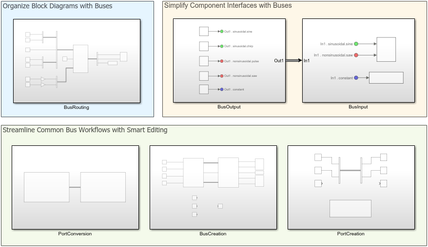
组合信号、消息或连接以简化模型外观。
- Bus-Capable Blocks
Identify the blocks that support virtual buses, nonvirtual buses, and arrays of buses.
以可视化方式对信号线分组
- 将信号或消息组合到虚拟总线中
创建总线以减少模块图中的信号线数量。 - Simplify Subsystem and Model Interfaces with Bus Element Ports
Group multiple lines into a bus at the input or output of a model component. - Display Bus Information
Display information about buses, such as signal hierarchy and whether the bus is virtual or nonvirtual. - Identify Automatic Bus Conversions
Recognize modeling patterns that cause hidden Bus To Vector and Signal Conversion blocks. - Programmatically Create Bus Element Ports
Add blocks for bus element ports and specify element attributes using MATLAB® functions.
修改和配置总线
- Modify Bus Hierarchy
Change the order and hierarchy of nested buses and their elements. - 为总线元素赋值
使用 Bus Assignment 模块替换分配给总线元素的信号。 - Specify Initial Conditions for Bus Elements
Specify bus element values as initial conditions for buses. - Share and Reuse Bus-Routing Blocks
Share blocks that create or interact with buses using subsystem references or custom libraries.
定义总线对象数据类型
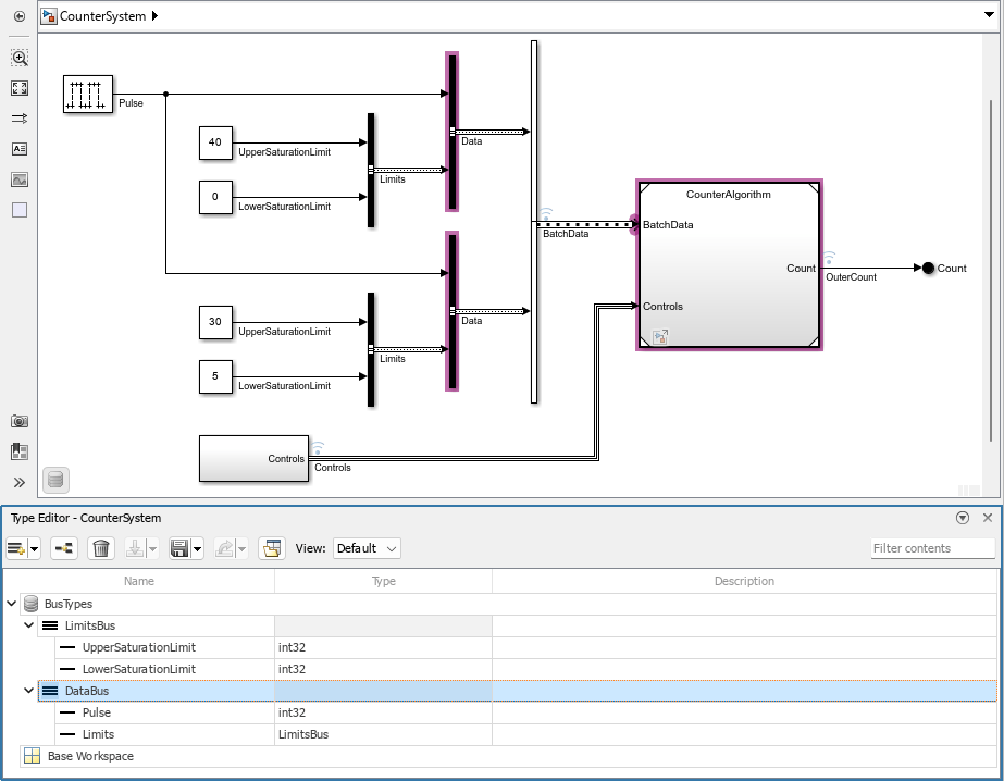
- 使用总线对象指定总线属性
创建可重用的总线定义,将其指定为总线的数据类型。 - 以编程方式创建 Simulink 总线对象
使用函数从其他对象、模块或 MATLAB 数据创建Simulink.Bus对象。
按功能对信号线分组
- Create Nonvirtual Buses
Create buses that appear in generated code and support modeling constructs such as arrays of buses. - Modify Sample Times for Nonvirtual Buses
Make the sample time of signals the same so that you can group them in a nonvirtual bus. - Generate Code for Nonvirtual Buses
Use a structure in code generation to represent a nonvirtual bus. Control data types of initial condition structure fields. - Inspect Generated Code for Nonvirtual Buses
Find nonvirtual buses in generated code for a simple model.
简化迭代处理
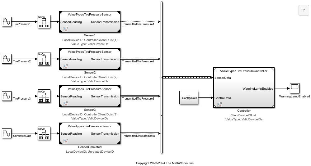
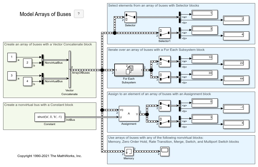
- 使用总线数组组合非虚拟总线
通过将具有相同数据类型的非虚拟总线合并为一个数组来简化模型以进行迭代处理。 - 使用总线数组
设置模型以使用总线数组来选择信号、为信号赋值、执行迭代处理、记录和加载信号以及初始化信号。 - Iteratively Process Nonvirtual Buses with Arrays of Buses
Update a model to use arrays of buses to apply the same algorithm to multiple nonvirtual buses with the same data type.
