Spin the Motors of a Parrot Minidrone Without Flying the Drone
This example shows you how to use Simulink® Support Package for Parrot® Minidrones to run a Simulink model that spins the propellers connected to motors of a Parrot minidrone, without flying the drone.
Introduction
Simulink Support Package for Parrot Minidrones enables you to create and run Simulink models on Parrot Rolling Spider and Parrot Mambo minidrones. The support package lets you design and simulate estimation and control algorithms for a minidrone in MATLAB® and Simulink, and auto-generates embedded c-code that you can use to actually fly the minidrone. After the flight, recorded data can be visualized and analyzed.
In this example, you will learn how to configure a simple Simulink model to generate code for a Parrot Rolling Spider and Parrot Mambo minidrone and run the generated code on the board. Using this example, you will spin the propellers connected to motors 1 and 3 for 2 seconds, and then spin the motors connected to motors 2 and 4 for 2 seconds, and so on till 20 seconds.
Prerequisites
If you are new to Simulink, we recommend completing the Interactive Simulink Tutorial.
Required Hardware
To run this example you will need the following hardware:
Parrot Rolling Spider Or Parrot Mambo minidrone with fully charged battery and propellers.
Micro USB type-B cable
Bluetooth® Low Energy (BLE) 4.0 support
Task 1 - Connect a Parrot Minidrone to Host Machine
In this task, you will connect a Parrot Rolling Spider/Parrot Mambo minidrone to host machine.
1. Check if the Parrot minidrone is connected via Bluetooth to the host machine by pinging the drone. To check whether Parrot Rolling Spider is connected or not, use the below command for ping.
ping 192.168.3.5
To check whether Parrot Mambo is connected or not, use the below command for ping.
ping 192.168.3.1
If the ping is successful, continue to Task 2.
2. On the MATLAB Home tab, click Add-Ons -> Manage Add-Ons.
3. Click the gear button as shown in the below figure.

4. Follow the instructions on the screen that appears, and ensure that the Rolling Spider/Mambo minidrone is connected via Bluetooth with the host machine.
Task 2 - Model the Algorithm to Spin the Propellers
This task shows how to use the input and output ports to model an algorithm to spin the motors.
1. Open the parrot_gettingstarted model.
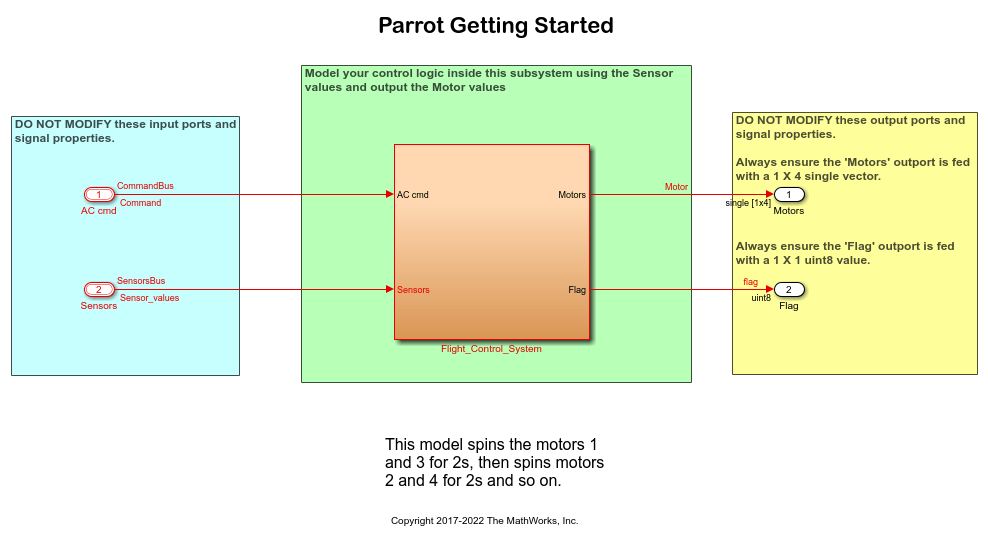
2. Notice the following points in the model:
There are 2 input ports in the model. The AC cmd input port gives a bus signal which mainly consists of 'position reference' and 'orientation reference' values along with other signals.
The Sensors input port contains data from sensors like accelerometer, gyroscope, ultrasonic, pressure, and optical flow data.

There are two output ports in the model. The Motors output port expects a vector of 4 single values.
The Flag output port expects a uint8 scalar value. Model an error condition and feed the value to the Flag output port. A non-zero value for this port indicates an error condition, and stops the drone flight. The non-zero value fed to the Flag outport is captured in the flight log generated after the flight.
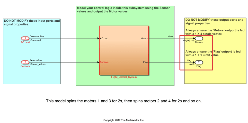
3. The Flight Control System subsystem models the logic of spinning of motors. Double click and open the Flight Control System subsystem.
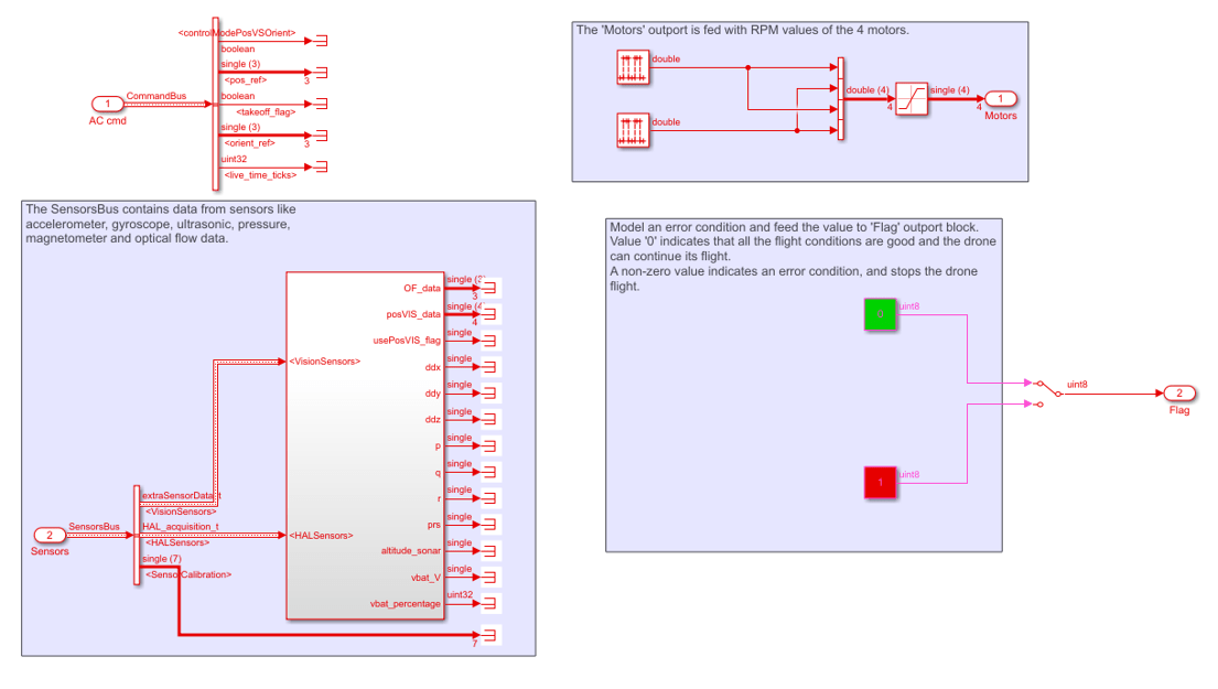
4. The logic used to spin alternate motors for 2 seconds each is mentioned below:
Two Pulse Generator source blocks with
 phase shift are used to spin alternate motors for 2 seconds each.
The input port values are not used in this model and hence are terminated by connecting the input port signals to the Terminator sink block.
Task 3 - Run the Generated Code on the Parrot Minidrone Using the Flight Control Interface
This task shows how to spin the motors of the Parrot minidrone using the above model.
1. In your parrot_gettingstarted model, click Build, Deploy & Start from Deploy section of Hardware tab. The model is loaded to the drone. After the build goes through successfully, a shared object is running on the drone, waiting for a connection from the PC.

2. If you have selected the Launch Parrot Flight Control Interface automatically after build option in the Configuration Parameters dialog box (Hardware Implementation pane > Target Hardware Resources > Build Options), the Parrot Flight Control UI opens automatically after the build goes through successfully. It can also be launched by clicking at the link displayed in the Diagnostic Viewer after model build is successful.
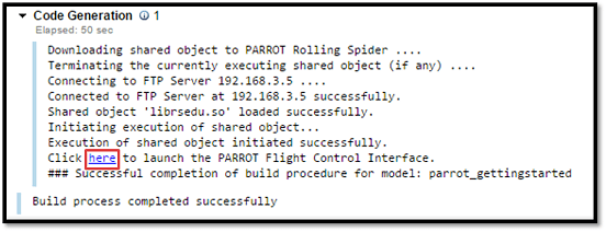
You can also launch the interface by executing Parrot_FlightInterface(Parrot_FlightInterface) at the MATLAB command window.
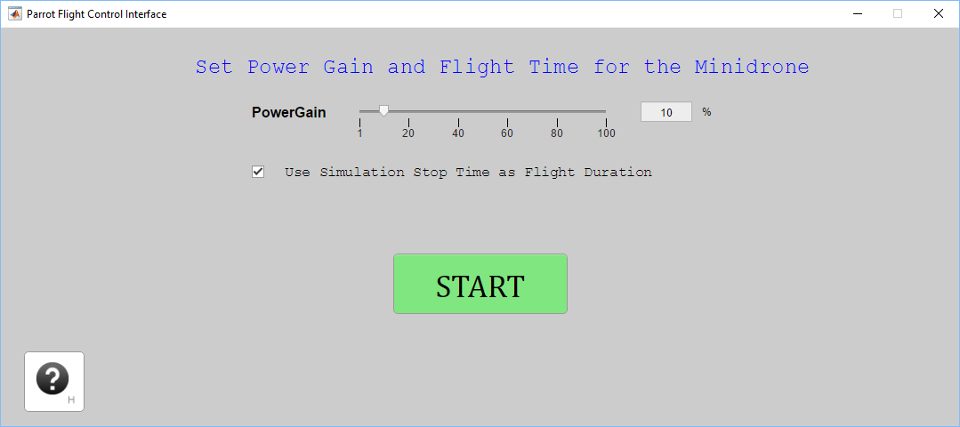
To know more about Parrot Flight Interface go to Using the Flight Control Interface to Start the Drone section.
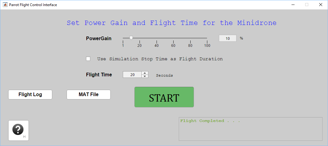
3. Set the power gain of the motors with the help of the slider. The power gain of the motors can be set to a percentage value from 0 to 100. It is recommended to set the power gain to a lower value first to test. The default powergain is 10%.
4. You can use the Simulation Stop Time for your model as the duration of flight for your minidrone. If you want to specify your own flight time, clear the checkbox and then set the flight time.
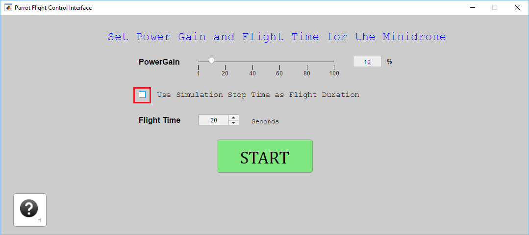
5. Click START. It might take a few minutes after which the motors start spinning. Observe that the two clockwise motors spin for 2s, and then the two counter-clockwise motors spin for 2s, and so on.
You can also observe that the Parrot Flight Control Interface is changed after you click START, and it displays STOP button.
The STOP button can be used for emergency shutdown of the drone's motors, if required.
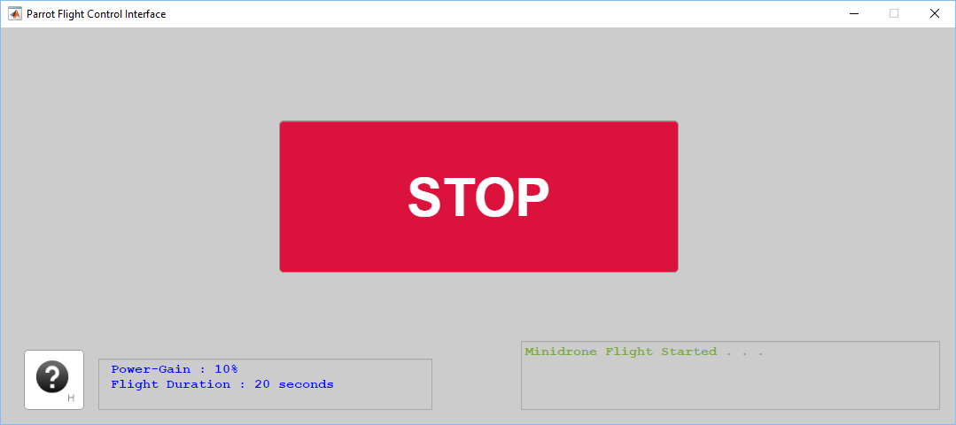
7. When the flight time (as defined in Step 4 above) is over or the motors have stopped spinning, the Parrot Flight Control Interface changes the display back to show the START button. Click Flight Log to obtain the flight log. A text file titled droneFlight.txt is downloaded to your current MATLAB directory.
8. You can change the power gain and flight time and start the drone flight again for the updated values by clicking START.
9. If you have Simulink Coder™ License, you can also download the MAT-File for the signals logged in the model. Enable MAT-File logging for your model and click Build Model to download the generated code on the minidrone. Click START to spin the motors. After the flight time is over, click MAT File to download the MAT-File on your current MATLAB directory.
Task 4 - Use Simulink Templates for Parrot Minidrone
In this Task, you will learn how to use the Simulink templates for Parrot Minidrones. Two templates are provided for the Simulink Support Package for Parrot Minidrones, namely, Code Generation template and Flight Simulation template.
1. Open the Simulink Start page.
2. From the Simulink Support Package for Parrot Minidrones templates, create a new Simulink model using Code Generation template.

The template is categorized into three main regions, namely, input, algorithm and output section.
3. Use the input ports Sensors and AC cmd, output ports Motors and Flag as mentioned in Task 2 above.
4. Open the 'Flight Control System' subsystem in your new model, and model your own controller logic by using the sensor values from the 'SensorBus' and output a  vector of single values to the Motors output port.
5. From the Simulink Support Package for Parrot Minidrones templates, create a new Simulink project using Flight Simulation template.
6. Use the new project to design your own controller in the 'Flight Control System' subsystem, simulate the 'slQuadcopter' to see your controller in action. To build and load the controller that you have designed on to the drone, click the Generate Flight Code shortcut in the Project Shortcuts tab.
Other Things to Try with Simulink Support Package for Parrot Minidrones
For Example:
1. Create and run a model that spins the motors 1 and 2, when the drone is tilted in forward direction, and spins the motors 3 and 4, when the drone is tilted in backward direction. Hint: Use the accelerometer data from the input port Sensors to determine the tilt angle.
2. Create and run a model that has the following characteristics.
Spin all the 4 motors
Model the logic in such a way that the model stops executing after 10 seconds. Hint: Use the 'live_time_ticks' signal from the AC cmd to keep track of time.
Stop running the model if the drone is tilted by more than
 in any direction. Hint: Use the accelerometer data from the input port Sensors to determine the tilt angle.
3. Fly the drone using the Simulink template as mentioned in Fly a Parrot Minidrone Using Hover Parrot Minidrone Simulink Template.
4. Create a new project using the Flight Simulation Template from the Parrot template library, which is on similar lines as of the above Code Generation Simulink Template for Image Processing for Parrot Minidrone demo. Create your own controller in the framework provided in the newly created project, simulate and fly the drone.