Specify Parameter Configuration for Full Coverage
About This Example
This example describes how to create and analyze a simple Simulink® model, for which you generate test cases that achieve decision coverage. However, in this example, achieving complete decision coverage is possible only when Simulink Design Verifier™ treats a particular block parameter as a variable during its analysis. This example explains how to specify parameter configurations for use with the analysis.
The following workflow guides you through the process of completing this example.
Task | Description | See... |
---|---|---|
1 | Construct the example model. | |
2 | Specify a variable as the value of a Constant block parameter. | |
3 | Constrain the value of the variable that the Constant block specifies. | |
4 | Generate test cases for your model and interpret the results. | |
5 | Simulate the test cases and measure the resulting decision coverage. |
Construct Example Model
Construct a simple Simulink model to use in this example:
Create an empty Simulink model.
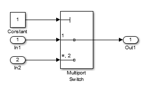
Copy the following blocks into the empty Simulink Editor:
From the Sources library:
From the Signal Routing library: A Multiport Switch block to provide simple logic
From the Sinks library: An Outport block to receive the output signal
Double-click the Multiport Switch block to access its dialog box and specify its Number of data ports option as
2
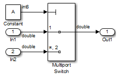
.Connect the blocks so that your model looks like the following.
On the Simulation tab, click the arrow on the right of the Prepare section and click Model Settings.
In the Configuration Parameters dialog box, select the Solver. Under Solver selection, set the Type option to
Fixed-step
, and then set the Solver option todiscrete (no continuous states)
.In the Diagnostics pane, set Automatic solver parameter selection to
none
.Click OK to apply your changes and close the Configuration Parameters dialog box.
Save your model as
ex_defining_params_example
for use in the next procedure.
Parameterize Constant Block
Parameterize the Constant block in your model by specifying a variable as the value of the Constant block's Constant value parameter:
Double-click the Constant block.
In the Constant value box, enter
A
.Click OK to apply your change and close the Constant block parameter dialog box.
Save your model.
Preload Workspace Variable
Preload the value of the MATLAB® workspace variable A
referenced by the
Constant block:
On the Modeling tab, select Model Settings > Model Properties.
Click the Callbacks tab.
In the
PreLoadFcn
, enter:A = Simulink.Parameter(int8(1)); A.Min = 1; A.Max = 2;
Click OK to close the Model Properties dialog box and save your changes.
Close your model.
Open your model.
When you open the model, the
PreLoadFcn
defines a variableA
of typeint8
whose value is 1.
Autogenerate Parameter Constraint
Use the Parameter Table to constrain variable
A
to specified values.
On the Apps tab, click the arrow on the right of the Apps section.
Under Model Verification, Validation, and Test, click Design Verifier.
On the Design Verifier tab, in the Prepare section, from the drop-down menu for the mode settings, click Settings.
In Configuration Parameters dialog box, select Design Verifier > Parameters and Variants.
Select Use parameter table.
Click Find parameters.
The Parameter Table is populated with parameters from your model. When possible, it autogenerates constraint values for each parameter, depending on the data type and location of the parameter in the model.
In this case, a row appears for the parameter
A
that you defined. The table row forA
displays the following information:In the Name column, the parameter name (
A
).In the Constraint column, the constraint specified on parameter
A
. The Parameter Table autogenerates the constraint values[1, 2]
.In the Value column, the value of
A
in the base workspace. This value is 1.In the Model Element column, the model component in which
A
resides (ex_defining_params_example/Constant
).In the Use column, a check box indicating whether the specified constraint values in the table are configured for analysis.
In the Parameter Table, in the row for parameter
A
, make sure that you select the Use check box.When you enable this parameter configuration, during Simulink Design Verifier analysis, the parameter
A
takes only theint8
values 1 and 2.In the Configuration Parameters dialog box, click OK.
Save your model.
Analyze Example Model
Analyze the model by using the parameter configuration you just created, and generate the analysis report:
On the Design Verifier tab, in the Mode section, select Test Generation. Click Generate Tests.
Simulink Design Verifier analyzes your model to generate test cases.
When the software completes its analysis, in the Simulink Design Verifier Results Summary window, click HTML to access detailed analysis report.
The software displays an HTML report named
ex_defining_params_example_report.html
.Keep the Results Summary window open for the next procedure.
In the Simulink Design Verifier report Table of Contents, click
Test Cases
.Click
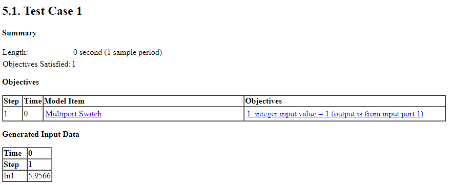
Test Case 1
to display the subsection for that test case.This section provides details about Test Case 1 that Simulink Design Verifier generated to satisfy a coverage objective in the model. In this test case, a value of 1 for parameter
A
satisfies the objective.
Simulate Test Cases
Simulate the generated test cases and review the coverage report that results from the simulation:
In the Simulink Design Verifier Results Summary window, select Create harness model.
The software creates and opens a harness model named
ex_defining_params_example_harness
.The block labeled
Inputs
in the harness model is a Signal Editor block that contains the test case signal. Double-click theInputs
block to view the test case signal in the block.In the harness model window, click the Run all (Coverage) button.
The Simulink software simulates each of the test cases in succession, collects coverage data for each simulation, and displays an HTML report of the combined coverage results at the end of the last simulation.
In the model coverage report, review the Summary section:
This section summarizes the coverage results for the harness model and its Test Unit subsystem. Observe that the subsystem achieves 50% decision coverage.
In the Summary section, click the
Test Unit
subsystem.The report displays detailed coverage results for the
Test Unit
subsystem.The summary section reveals that the Multiport Switch block achieves 50% decision coverage because the test cases exercise each of the switch pathways.
See Also
Extend Existing Test Cases After Applying Parameter Configurations