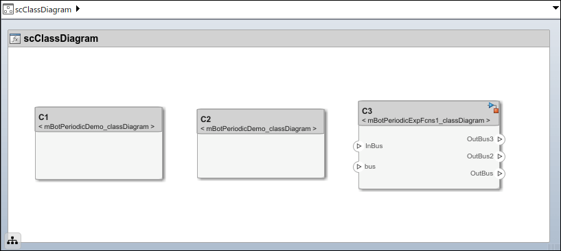
Class Diagram View of Software Architectures
Use class diagrams to display a graphical representation of the structure of a software architecture model. You can also use spotlight views to analyze component dependencies and hierarchy, and you can use component hierarchy views to visualize the component hierarchy as a tree diagram. For more information, see Create Spotlight Views and Display Component Hierarchy and Architecture Hierarchy Using Views.
A class diagram is a graphical representation of a static structural model that displays unique architecture types of the software components optionally with software methods and properties.
Class diagrams capture one instance of each referenced model and show relationships between them. A component diagram view can be optionally represented as a class diagram for a software architecture model.
Software Architecture with Class Diagram View
This example uses a software architecture model with functions, stereotypes, and properties to explore class diagrams in the Architecture Views Gallery. Open the model to follow the steps in this tutorial.
Interact with Class Diagram View
Simulate the model to compile it and populate functions. On the toolstrip, click Run. Alternatively, update the model to compile it by navigating to Modeling > Update Model.
To open the Architecture Views Gallery, navigate to Modeling > Architecture Views.
From the View Browser, select the View 1 view.
To open the class diagram view, click Diagram > Class Diagram.
The class diagram consists of:
A class box for each unique component type, including reference components.
A class box as the root that corresponds to the root architecture of the top model.
Composition connections between the types.
If there are multiple instances of the same type of component, for example, multiple components that reference the same model across the model hierarchy, then the type of the component is still represented as one unique box. The component will also relate to its parents and children with multiplicity representations.
You can select Hide methods to simplify the output by removing software functions from the diagram. Select Hide properties to hide information about stereotypes and property values applied to the components.
Edit Function Properties Using Property Inspector
You can select functions in the class diagram view of a software architecture and edit properties of the selected functions using the Property Inspector.
To edit function properties:
Select a function in a root architecture, component architecture, or service interface.
Edit the function properties in the Property Inspector of the view. Properties can include the function name, function stereotype, or, for service interfaces, the function prototype.
When you finish editing, you can see the updated function in the class diagram view.
When you modify the properties of a function in the class diagram view, your changes also get propagated to the Functions Editor and the Interface Editor.
Client-Server Interfaces in Class Diagram View
Class diagrams display service (client-server) interfaces. The diagram shows the service interface classes and available services.
In this example, a software architecture has two components that are connected with client and server ports. The Interface Editor shows the interface assigned to the client and server ports.
model = systemcomposer.openModel('SoftwareArchitectureClientServer'); set_param('SoftwareArchitectureClientServer','SimulationCommand','Update');
openViews(model)
To open the class diagram view, from the View Browser, select ServiceInterfaces
.
This is the class diagram view of the software architecture.
The icon on the upper right and the decoration bar of the class distinguishes the service interface class.
The service interface class contains function prototypes as services.
The diagram displays an aggregation connection for the client port.
The diagram displays a composition connection for the server port.