Main Content

Field-Oriented Control of PMSM with Hall Sensor Using C2000 Processors

This example implements the field-oriented control (FOC) technique to control the speed of a three-phase permanent magnet synchronous motor (PMSM). The FOC algorithm requires rotor position feedback, which is obtained by a Hall sensor. For details about FOC, see Field-Oriented Control (FOC) (Motor Control Blockset).

A closed-loop FOC algorithm is used to regulate the speed and torque of a three-phase PMSM. This example uses C28x peripheral blocks from the C2000™ Microcontroller Blockset and MCB library blocks from Motor Control Blockset™.

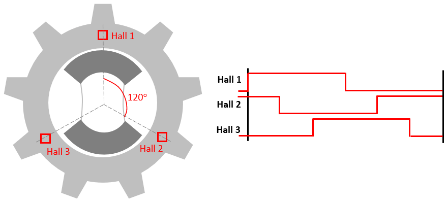
This example uses the Hall sensor to measure the rotor position. A Hall effect sensor varies its output voltage based on the strength of the applied magnetic field. A PMSM consists of three Hall sensors located electrically 120 degrees apart. A PMSM with this setup can provide six valid combinations of binary states (for example, 001,010,011,100,101, and 110). The sensor provides the angular position of the rotor in the multiples of 60 degrees, which the controller uses to compute the angular velocity. The controller can then use the angular velocity to compute an accurate angular position of the rotor.

Required Hardware

This example supports these hardware configurations. Use the target model name (highlighted in bold) to open the model for the corresponding hardware configuration, from the MATLAB® command prompt.

  • Three-phase PMSM with optional HALL sensors attached to connector J4 of the DRV8312-C2-KIT board or connector J12 of LAUNCHXL-F280049C.

For connections related to the preceding hardware configuration, see Hardware Connections.

Available Models

The example includes these models:

Note: For F28069M control card, LAUNCHXL-F28069M controller and LAUNCHXL-F28379D controller, refer to Field-Oriented Control of PMSM Using Hall Sensor (Motor Control Blockset).

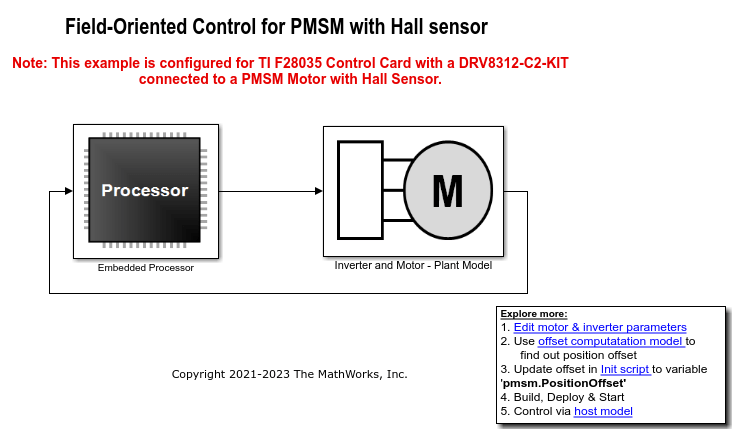
You can use these models for both simulation and code generation. Open the mcb_pmsm_foc_hall_f28035 model.

You may need to change the model parameters to fit your specific motor. Match motor voltage and power characteristics to the controller.

A conventional voltage-source inverter drives motor. The controller algorithm generates six pulse width modulation (PWM) signals using a vector PWM technique for six power switching devices. The inverter measures the current of the two motor inputs (ia and ib) input currents of the motor (ia and ib) using two analog-to-digital converters (ADCs) and sends the measurements to the processor.

Peripheral Block Configurations

Set the peripheral block configurations for this model. Double-click on the blocks to open block parameter configurations. You can use the same parameter values if you want to run this example for other hardware boards.

  • ePWM Block configuration

  • ADC Block configuration

The algorithm in this example uses an asynchronous scheduling. The pulse width modulation (PWM) block triggers the ADC conversion. At the end of conversion, the ADC posts an interrupt that triggers the main FOC algorithm. For more information, refer ADC Interrupt Based Scheduling.

Configure the Model

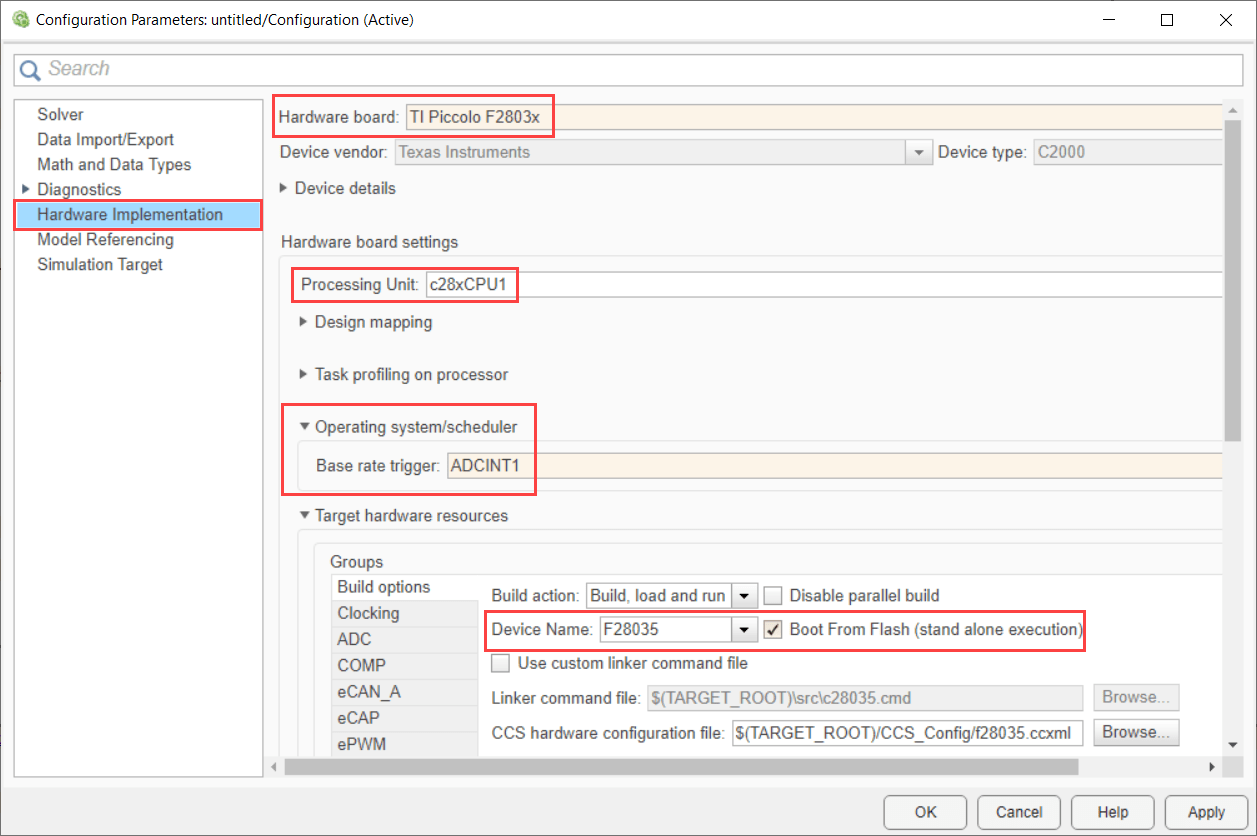
1. Open the mcb_pmsm_foc_hall_f28035 model. This model is configured for TI Piccolo F2803x hardware.

2. To run the model on other TI C2000 processors, first press Ctrl+E to open the Configuration Parameters dialog box. Then, select the required hardware board by navigating to Hardware Implementation > Hardware board.

3. The following screenshots show the scheduler configurations performed in the model. You can use the same parameter values if you want to run this example for other hardware boards.

Note:

  • Sampling rate of the ADC block should be same as the base rate of the model determined by the PWM period of the ePWM block.

  • Base rate trigger selection should be same as the interrupt triggered by the ADC module. For more information, see Model Configuration Parameters for Texas Instruments C2000 Processors.

  • Ensure that the Default parameter behavior is set to Inlined (Configuration Parameters > Code Generation > Optimization).

4. Ensure that the baud rate is set to 1.5e6 bits/sec.

Note: For F28335 processor you need to use external FTDI for serial communication.

Required MathWorks® Products

To simulate model:

For the models: mcb_pmsm_foc_hall_f28035, mcb_pmsm_foc_hall_f28335 and mcb_pmsm_foc_hall_f283049c

  • Motor Control Blockset™

  • Fixed-Point Designer™

To generate code and deploy model:

For the models: mcb_pmsm_foc_hall_f28035, mcb_pmsm_foc_hall_f28335 and mcb_pmsm_foc_hall_f283049c

  • Motor Control Blockset™

  • Embedded Coder®

  • C2000™ Microcontroller Blockset

  • Fixed-Point Designer™

Prerequisites

  • If you obtain the motor parameters from the datasheet or other sources, update the motor parameters and inverter parameters in the model initialization script associated with the Simulink® models. For instructions, see Estimate Control Gains and Use Utility Functions (Motor Control Blockset).

Simulate Model

This example supports simulation. Follow these steps to simulate the model.

1. Open a model included with this example.

2. Click Run on the Simulation tab to simulate the model.

3. Click Data Inspector on the Simulation tab to view and analyze the simulation results.

Generate Code and Deploy Model to Target Hardware

This section instructs you to generate code and run the FOC algorithm on the target hardware.

This example uses a host and a target model. The host model is a user interface to the controller hardware board. You can run the host model on the host computer. The prerequisite to use the host model is to deploy the target model to the controller hardware board. The host model uses serial communication to command the target Simulink model and run the motor in a closed-loop control.

1. Simulate the target model and observe the simulation results.

2. Complete the hardware connections.

3. The model automatically computes the ADC (or current) offset values. To disable this functionality (enabled by default), update the value 0 to the variable inverter.ADCOffsetCalibEnable in the model initialization script.

Alternatively, you can compute the ADC offset values and update it manually in the model initialization scripts. For instructions, see Open-Loop Control of 3-Phase AC Motors Using C2000 Processors.

4. Compute the hall sensor offset value and update it in the model initialization scripts associated with the target model. For instructions, see Hall Offset Calibration for PMSM Motor.

5. Open the target model for the hardware configuration that you want to use. If you want to change the default hardware configuration settings for the model, see Model Configuration Parameters (Motor Control Blockset).

6. Click Build, Deploy & Start on the Hardware tab to deploy the target model to the hardware.

7. Click the host model hyperlink in the target model to open the associated host model. Open the mcb_pmsm_foc_host_model host model.

For details about the serial communication between the host and target models, see Host-Target Communication (Motor Control Blockset).

8. Set the parameter Port of the following blocks in the mcb_pmsm_foc_host_model model to match the COM port of the host computer:

  • mcb_pmsm_foc_host_model > Host Serial Setup.

  • mcb_pmsm_foc_host_model > Serial Communication > Host Serial Receive.

  • mcb_pmsm_foc_host_model > Serial Communication > SCI_TX > Host Serial Transmit.

9. Update the Reference Speed value in the host model.

10. Click Run on the Simulation tab to run the host model.

11. Change the position of the motor switch to Start, to start running the motor.

12. Observe the debug signals from the serial communication, in the Time Scope of host model. Use Debug signals to visualize different debug signals in SelectedSignals.

More About: