Serial Transmit
R2026bSerial Transmit block
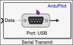
To add a block to a model, double-click the canvas and start typing the block name. Then, select the block from the list.
Libraries:
UAV Toolbox Support Package for ArduPilot Autopilots /
Peripheral Blocks
Description
Add-On Required: This feature requires the UAV Toolbox Support Package for ArduPilot Autopilots add-on.
The Serial Transmit block transmits data over a serial communication interface (SCI) on supported ArduPilot® targets. The block accepts input values as an N-by-1 or 1-by-N array.
Use this block to transmit data from a Simulink®model to external devices or subsystems over a serial connection on ArduPilot hardware. Typical applications include, transmitting sensor or control data to external serial peripherals, debug or telemetry data transmission, and communication with companion computers or serial devices.
The Serial Transmit block is supported only on ArduPilot based flight controllers. It is not supported for SITL board configuration or ArduPilot Host Target autopilot configuration.
Note
When you use this block to send serial data, set the SERIALx_PROTOCOL parameter of the ArduPilot autopilot to an unused protocol value. For instance, using Mission Planner, set the parameter to 55. When SERIALx_PROTOCOL has its default value, ArduPilot assigns a built-in driver to the port and the serial block cannot access it.
Examples
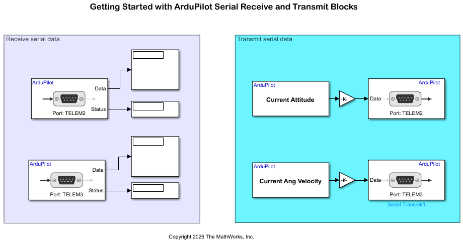
Getting Started with ArduPilot Serial Receive and Transmit Blocks
Configure two ArduPilot® telemetry ports for bidirectional loopback communication using Serial Transmit and Serial Receive blocks in Simulink®.
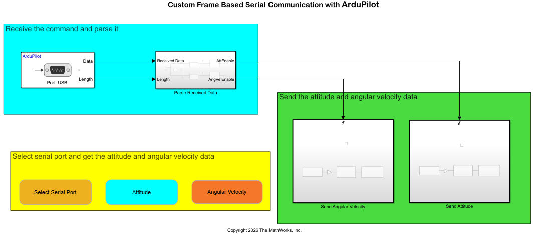
Send and Receive Custom Frame-Based Serial Data with ArduPilot
Send and receive custom frame-based serial data between a host computer and an ArduPilot® flight controller using the UAV Toolbox Support Package for ArduPilot Autopilots®. The example uses a request-response protocol in which a MATLAB® script on the host computer sends a data request, and the flight controller responds with the requested attitude or angular velocity data.
Ports
Input
Parameters
Version History
Introduced in R2026b

